72
Q26 Camera Manual: Installation
2.2.2 Procedure
1. Install and prepare the network connection.
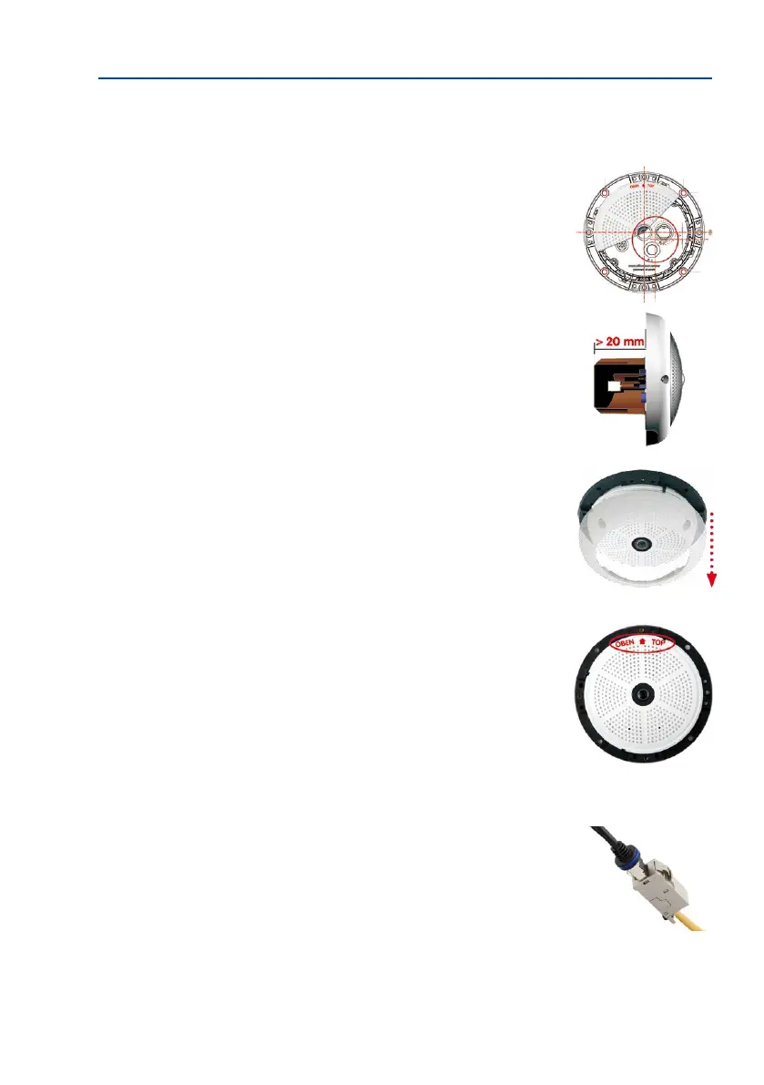
2. Installtheush-mountedwalloutlet: The pre-installed
cable attached to the camera must be connected with the
on-site network cable. For installation without accessories,
a ush-mounted wall outlet must be installed rst, in order
to provide a connection. The cabling is perfectly protected
and cannot be seen or damaged. The camera cannot be
mounted directly on top of protruding wall outlets. Use the
camera drilling template (available for downloading from
www.mobotix.com) to mark the position of the wall out-
let for the desired camera position.
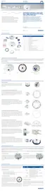
3.
Remove the outer shell: Remove all four Allen screws using
the supplied Allen wrench and li o the outer shell.
4. Drill the holes: Drill the holes for the supplied screw
anchors (see drilling template). Remember to take the
proper direction of the camera into consideration (OBEN
/ TOP arrow pointing upwards for wall installation, or in
the direction of the longer wall for ceiling installation in
rectangular rooms).
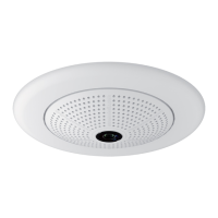
5. Connect the cable: Connect the on-site network cable
to the camera patch cable using a standard connector.
RJ45 patch cable: 50 cm
(19.7 in) cable incl., other
lengths available from
MOBOTIX as accessories
Due to the space required
for cable and connectors,
we recommend a ush-
mounted wall outlet with
an installation depth of
at least 20 mm/8 in