– 38 –
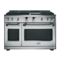
5. Slide the switch off the switch plate.
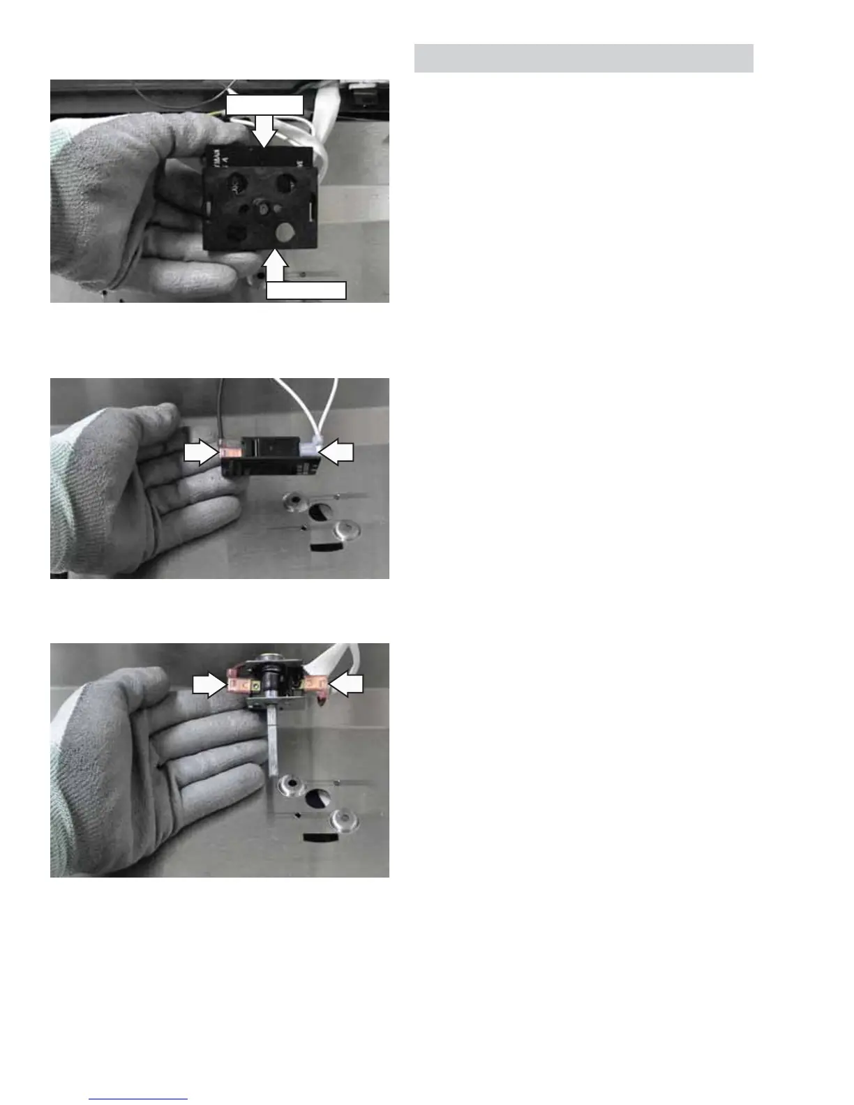
6. Remove the wires from the LED switch.
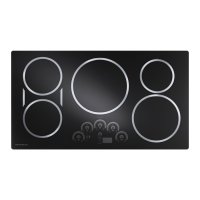
7. Remove the wires from the control.
8. Slide the capillary out of the griddle burner box.
LED Switch
Switch Plate
Grill and Griddle Ignition Systems
The grill and griddle burners are ignited by a
glowbar ignition system. The igniter is a Norton style
rectangular glowbar. The grill and griddle ignition
circuits consist of the control, an igniter, and a
safety valve. These components are wired in series
for each cooking function.
The igniter glowbar and it’s protective cage are one
assembly on this Norton-style igniter. The round
Carborundum igniter CANNOT be substituted for the
rectangular Norton Igniter.
The most important points to know about the
ignition system are:
• THE IGNITER RESISTANCE DECREASES AS THE
IGNITER SURFACE TEMPERATURE INCREASES.
• THE SAFETY VALVE OPERATES BY CURRENT, NOT
VOLTAGE.
From a cold start, the ignitor needs 20-60 seconds,
with voltage applied, to reduce its electrical
resistance fl ow in the series circuit. This is the
required current fl ow needed for the safety valve
to open in order to supply gas to the burner. The
glowbar should provide a steady current fl ow
between 3.2 and 3.6 amps fl owing in the circuit.
The igniter will remain energized at all times during
burner operation. If the igniter glows red but does
not draw at least 2.9 amps, the fault is usually with
the igniter, not the valve.