– 64 –
Oven Control Logic Board
The oven control logic board consists of several
boards and a frame. The logic board controls oven
operation through user input and feedback from the
oven sensor and switches. The oven control logic
board is attached to the inside center of the control
panel, and is only available as a complete assembly.
It is necessary to lower the control panel to replace
the oven control logic board.
To remove the oven control logic board:
1. Remove the oven control knobs.
2. Remove the 3 Phillips-head screws (6 on double
oven models), that attach the oven control logic
board to the control panel.
3. Place the control panel in the service position.
(See
Control Panel.)
4. Disconnect wire harness and remove harness
from clip, then carefully lift the assembly from
the control panel.
Disconnect
Oven Logic
Board
Clip
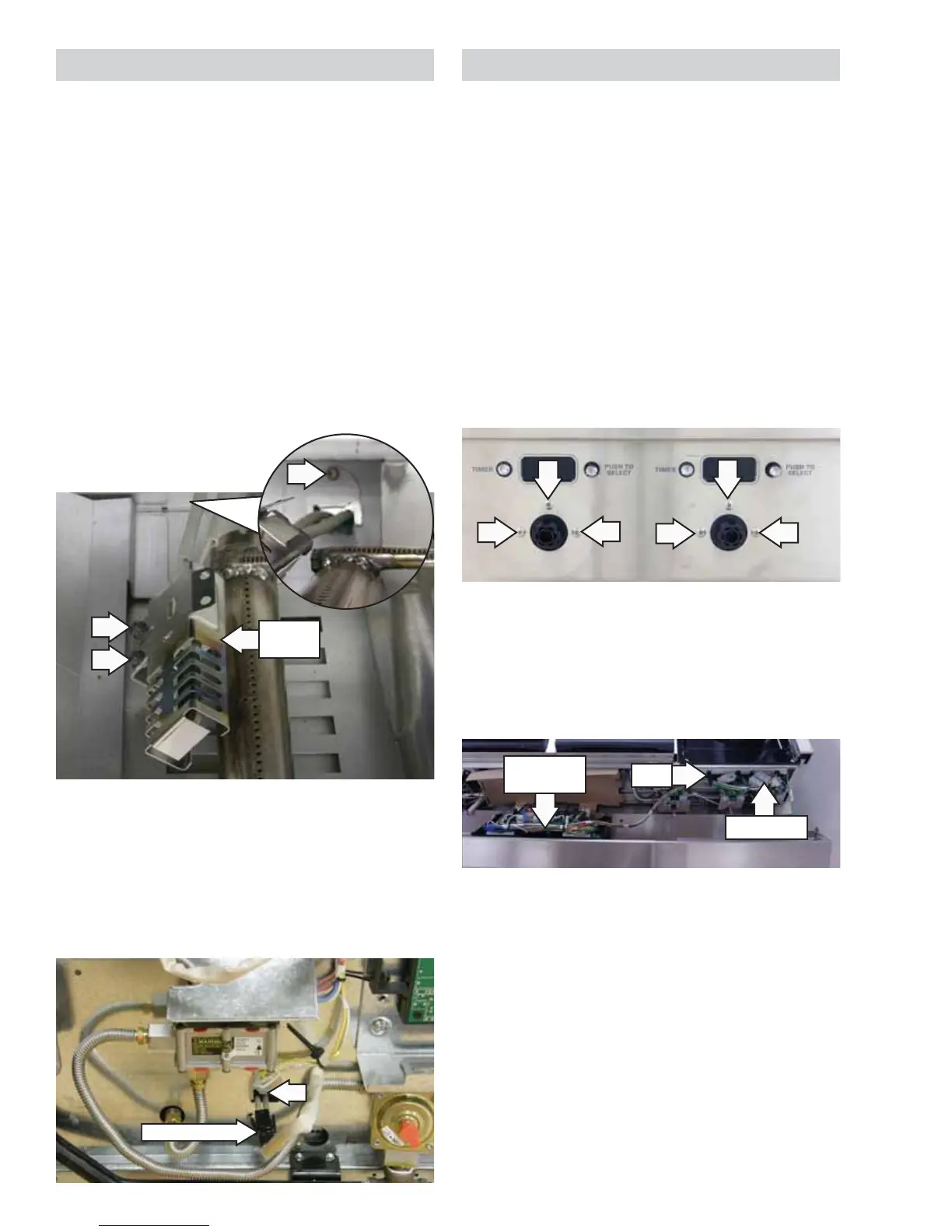
Oven Glowbar Ignitor
Note: The glowbar ignitor replacement is similar
for the main and companion ovens. The main oven
bake burner ignitor is shown; companion oven and
broil ignitor are similar.
To remove the glowbar ignitor:
1. Access the glowbar ignitor as outlined in the
oven bake or broil burner procedure. (See Oven
Bake Burner or Oven Broil Burner.)
2. Remove the two 1/4-in. hex-head screws that
secure the glowbar ignitor to the burner.
3. Remove the 1/4-in. hex-head screw and cover
plate from the back of the burner box (bake
burner only).
Disconnect
Glowbar
Igniter
4. Remove the back panel from the range. (See
Back Panel.)
5. Remove the 1/4-in. hex-head screw and cover
plate from the back of the range, if equipped.
6. Disconnect the glowbar ignitor wiring harness
and pull connector into the oven cavity.