– 50 –
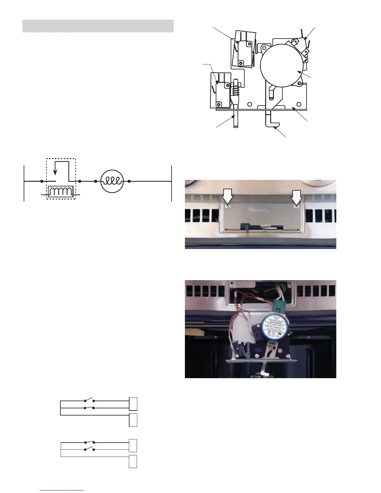
Lock Assembly
The motorized door lock assembly is located above
the oven. The assembly consists of a lock motor
cam and switch assembly, lock hook, mounting
plate, door switch, spring and plunger.
The lock motor is energized when the control is set
for Clean, and Clean Time is selected. The K13 relay
contact will close and complete the circuit that
supplies the voltage to the lock motor.
Door locking or unlocking will close and complete
the circuit that supplies voltage to the lock motor.
C MDL
N
L
LOCK RELAY
LOCK
MOTOR
Door Locking/Unlocking Strip Circuit
Note: To enable proper operation of the door
lock, ensure that the door jamb switch contacts
“common” to “normally closed” are closed (door
closed position). This enables power to be delivered
when the door lock closes.
The cam on the motor performs two functions:
1. Positions the lock hook in the door to prevent
opening during the Clean operation.
2. Operates the lock switches, which tell the
control if the door is unlocked or locked, and
ready for the Clean operation.
Note: When the door is either being locked or
unlocked, both the lock and unlock switches are
in the open position. The LOCKED AND UNLOCKED
diagrams are representative of a single oven. On
double oven models, the diagrams apply to both
models, except for the pin position.
(See Oven Sensor
and Door Switch Test section for reference to double
ovens.)
J16
J17
Y
P
P
P
B
4
3
1
LOCK
UNLOCK
LOCKED
J16
J17
Y
P
P
P
B
4
3
1
LOCK
UNLOCK
UNLOCKED
(Continued next page)
Unlock
Switch
Lock
Switch
Lock
Motor
Door
Switch
Lock
Hook
Spring and
Plunger
Mounting
Plate
The lock assembly is attached to the oven frame by
two 1/4-in. hex-head screws.
There is suffi cient wiring to pull the door lock
assembly completely out for service.