– 63 –
Oven Burner Ignition System
The ignitor is a "Norton" style rectangular glowbar.
The ignition circuit consists of the thermostat, the
igniter, and the oven safety valve (gas valve). The
three components are wired in a series.
The most important points to know about the
ignition system are:
1. THE IGNITOR RESISTANCE DECREASES AS THE
IGNITER SURFACE TEMPERATURE INCREASES.
2. THE SAFETY VALVE OPERATES BY CURRENT, NOT
VOLTAGE.
From a cold start, the ignitor needs 20-60 seconds,
with voltage applied, to reduce its electrical
resistance fl ow in the series circuit. This is the
required current fl ow needed for the safety valve
to open to supply gas to the burner. The glowbar
should provide a steady current fl ow between 3.2
and 3.6 amps fl owing in the circuit. The igniter
will remain energized at all times during burner
operation. If the igniter glows red but does not draw
at least 2.9 amps, the fault is usually with the igniter,
not the valve. Always check the oven shut-off valve
for a "No Oven" condition.
Companion Oven
To remove the companion oven broil burner:
1. Remove the oven door.
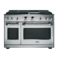
2. Remove the two 1/4-in. hex-head screws from
the broil cover.
Note: The companion oven is similar to the main
oven.
3. Remove the back panel from the range. (See
Back Panel.)
4. Remove the cover, fl ex tube, glowbar ignitor, and
screws from rear broil bracket of the companion
oven as outlined in steps 3 thru 7 of the main
oven. (See Main Oven, this section.)
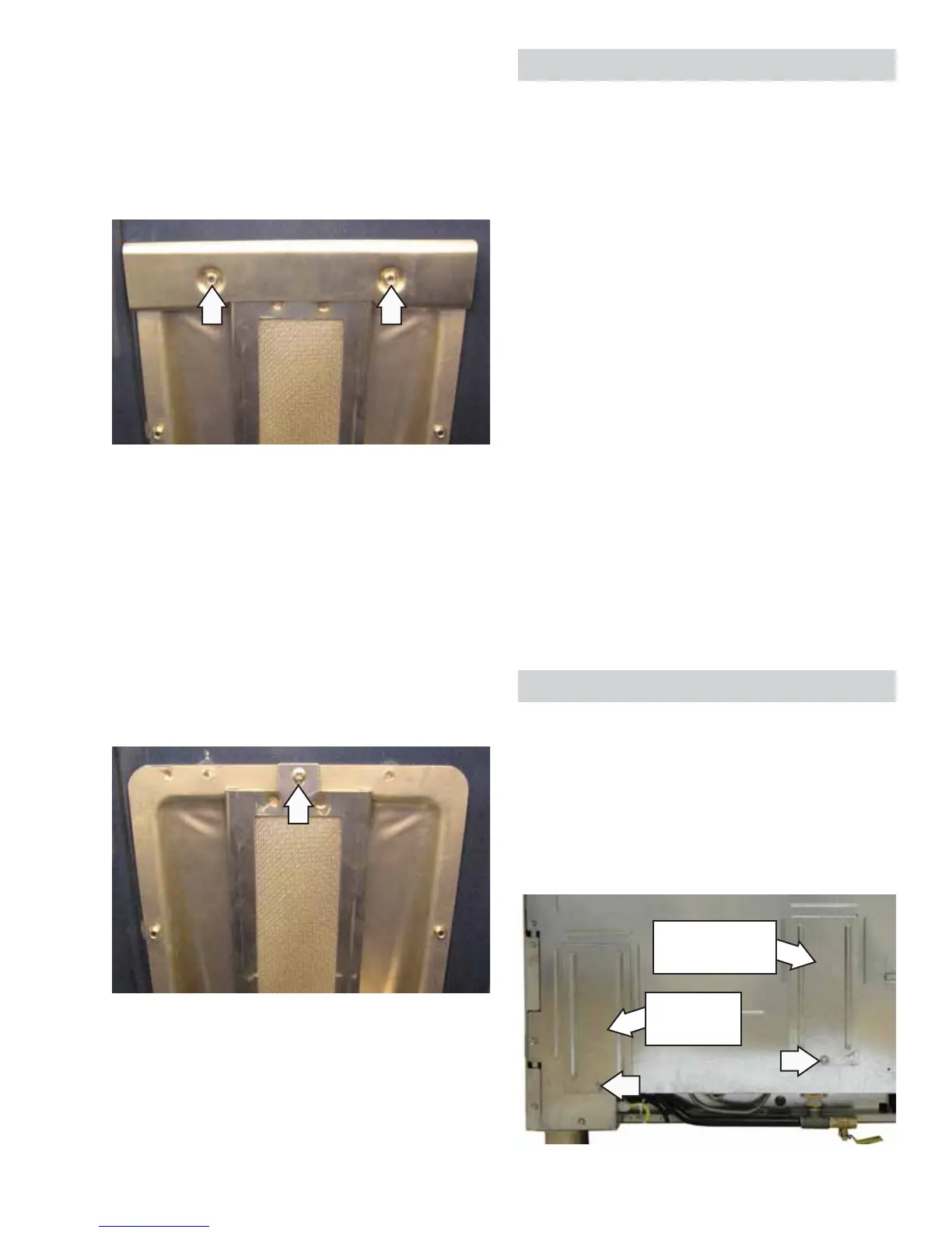
5. Remove Phillips-head screw from the broiler and
carefully pull out of oven.
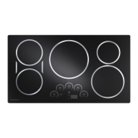
Oven Relay Board Access
The Relay Board is located on the range back.
Access it by removing the 1/4-In. hex-head screw
from the edge of the trap door. Remove the trap
door and lift the insulating paper covering the relay
board to access.
Note: Both the main and companion oven relay
boards are accessed using the same method.
Trap Door for
Main Oven
Relay Board
Trap Door for
Companion Oven
Relay Board