– 41 –
Surface Burner
Note: The following describes the procedure to
remove a single burner. The procedure to remove
the remaining burners is identical.
To remove the burner:
1. Remove the burner base. (See Surface Burner
Base.)
2. Remove the surface burner pan. (See Surface
Burner Pan.)
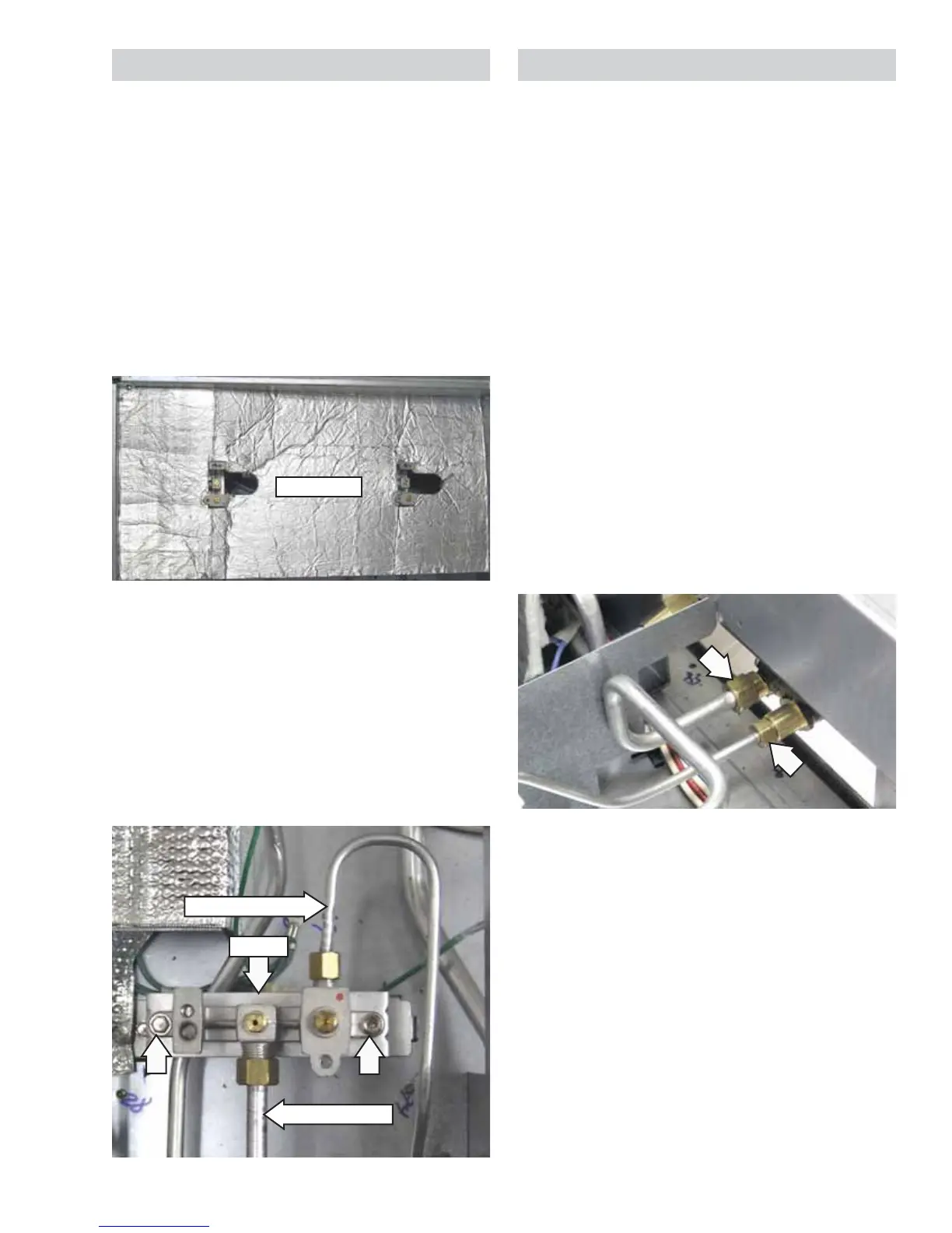
3. Remove the heat barrier by lifting it out of the
burner box.
4. Remove the 9/16-in. nut and separate the main
gas tube from the burner.
5. Remove the 7/16-in. nut and separate the
simmer gas tube from the burner.
6. Remove the two 1/4-in. hex-head screws that
attach the burner to the burner bracket.
Burner
Simmer Gas Tube
Main Gas Tube
Heat Barrier
Heat barrier as viewed from side
Surface Burner Valve and Switch
Each surface burner valve utilizes a switch. When a
burner knob is turned to the ON position, the valve
switch closes and activates the spark module and
the LED light. Each surface burner valve switch is
installed on the front of the burner valve body. The
switches are all wired to a single harness and are
replaced as one assembly. It is necessary to remove
the valve to access the switch.
Note: The following describes the procedure to
remove a single burner valve and switch. The
procedure to remove the remaining valves and
switches is identical.
To remove the surface burner valve and switch:
1. Remove the burner pan located over the valve
and switch to be replaced. (See Surface Burner
Pan.)
2. Remove the heat barrier by lifting it out of the
burner box.
3. Remove the 7/16-in. nut and the 9/16-in. nut
from the valve.
4. Remove the Phillips-head screw and the
indicator light assembly from the valve bracket.
(See
Indicator Light Assembly.)
(Continued next page)