Specification TWINsync module
13
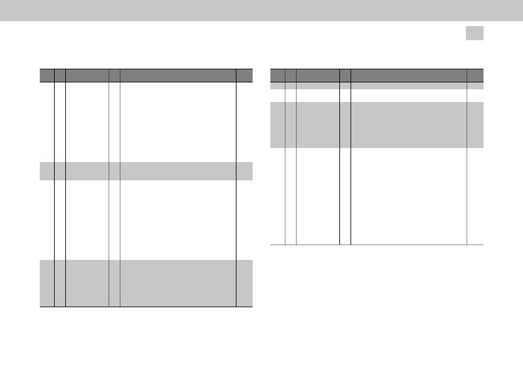
4 Description of parameters
ID no.: CB08759-001Date: 03/2023
moog
ID
Sub
ID
Name Unit Description
Data
type
P
2619
TOPT_TWIN_
CommStatus (ro)
bits UInt16
P
2623
ns
Bit status of communication (not used with extended
mapping)
0: No error
1: Communication error, communication lost (error frames >
P2613)
2: switching-frequency discrepancy
3: master / slave mode conflict
4: -
5: Different DriveCom states between master and slave
6: dSpace mode control error (different mode detected –
only dSpace modes)
7-15: -
TWINsync system load. Actual load of TWINsync
communication (receive and transmit)
and handling of protocol data (mapping)
Float32
P2651
TOPT_TWIN_
SystemLoad (ro)
TOPT_TWIN_Config bits
Configuration of TWIN special function (default not
necessary).
Bit:
0: -
1: Shift TWIN RX/TX handling to next 16kHz control cycle
(possibly saves CPU load of the position loop cycle).
2: Disable DriveCom state handling on TWIN master
(disable check of slave status).
Normally master waits until slave is switched on and is in
state 'Operation- Enabled',
after this, the master switches on its control.
3-15: -
UInt32
P2701 TOPT_TWIN_
SyncSel
wet Synchronization selection (TWIN/fieldbus)
0 = SLAVE_SYNC_ISR, TWINslave, sync by TWIN (mode
1)
1 = SLAVE_SYNC_COM, TWINslave, sync by external
fieldbus (com opt)
2 = SLAVE_SYNC_ENC, TWINslave, sync by TWIN (mode
2)
3 = MASTER_NO_COM_SYNC, TWINmaster, no sync by
UInt16
Table 4.1: Configuration parameters of the TWINsync technology option card
(continued)
ID
Sub
ID
Name Unit Description
Data
type
external fieldbus (com opt)
P2709 0...1 TOPT_TWIN_
PhyLinkConfig
physical and link configuration
P2709 0 Baud rate baud rate selection
0 = 4 M
1 = 2 M
2 = 1 M
3 = 800 k
4 = 500 k
5 = 400 k
6 = 250 k
UInt16
P2709 1 Frame size frame size selection
(sm) = (standard mapping)
(em) = (extended mapping)
0 = 10 byte PDO (sm) or 14 byte EXT_PDO (em)
1 = 8 byte PDO (sm) or 12 byte EXT_PDO (em)
2 = 6 byte PDO (sm) or 10 byte EXT_PDO (em)
3 = 4 byte PDO (sm) or 8 byte EXT_PDO (em)
4 = 2 byte PDO (sm) or 6 byte EXT_PDO (em)
5 = 0 byte PDO (sm) or 4 byte EXT_PDO (em)
6 = 12 byte PDO (sm) or 16 byte EXT_PDO (em)
7 = 14 byte PDO (sm) or 18 byte EXT_PDO (em)
8 = 16 byte PDO (sm) or 20 byte EXT_PDO (em)
9 = 18 byte PDO (sm) or 22 byte EXT_PDO (em)
10 = 20 byte PDO (sm) or 24 byte EXT_PDO (em)
11 = 22 byte PDO (sm) or 26 byte EXT_PDO (em)
12 = 24 byte PDO (sm) or 28 byte EXT_PDO (em)
13 = 26 byte PDO (sm) or 30 byte EXT_PDO (em)
UInt16
Table 4.1: Configuration parameters of the TWINsync technology option card
(continued)
wet : Value replacement text
ro : read-only
rw : read/write
(sm) : standard mapping
(em) : extended mapping