Specification TWINsync module
40
6 TWINsync operation modes
ID no.: CB08759-001Date: 03/2023
moog
The following figure shows the process data interface between the master and slave
drives in the operation mode: Gantry application
Static mapping
MSD
Slave
MSD
Master
Checksum
Communication state P2617
Mapping by operation mode
Gantry application
Position setpoint
Speed setpoint
Actual torque value
Actual position value
Control word P2611
Status word P2612
Actual speed value
Checksum
Communication state P2617
Figure
6.13:
Process
data
interface,
gantry
application
6.2.13 Extended Mapping Mode
Extended mapping was introduced for general synchronization tasks. It allows any
transfer of scope data or mappable parameter data (in summary: so-called
“ParaScope objects”). Ideally, in combination with iPLC applications on master and
slave. It is theoretically possible to write to scope data: the application must be
created with corresponding foresight.
Position
control
Speed
control
Digital
filter
Current
control
Filter/
Observer
Flux
control
Interpolation
and feed-forward
control
Position
control
Speed
control
Filter/
Observer
Interpolation
and feed-forward
control
1
+
-
P 2583
MPRO_TWIN_SlaveInvert
Digital
filter
Current
control
Flux
control
P 2581
MPRO_TWIN_MasterTorqueTF
P 2582
MPRO_TWIN_MasterSpeedTF
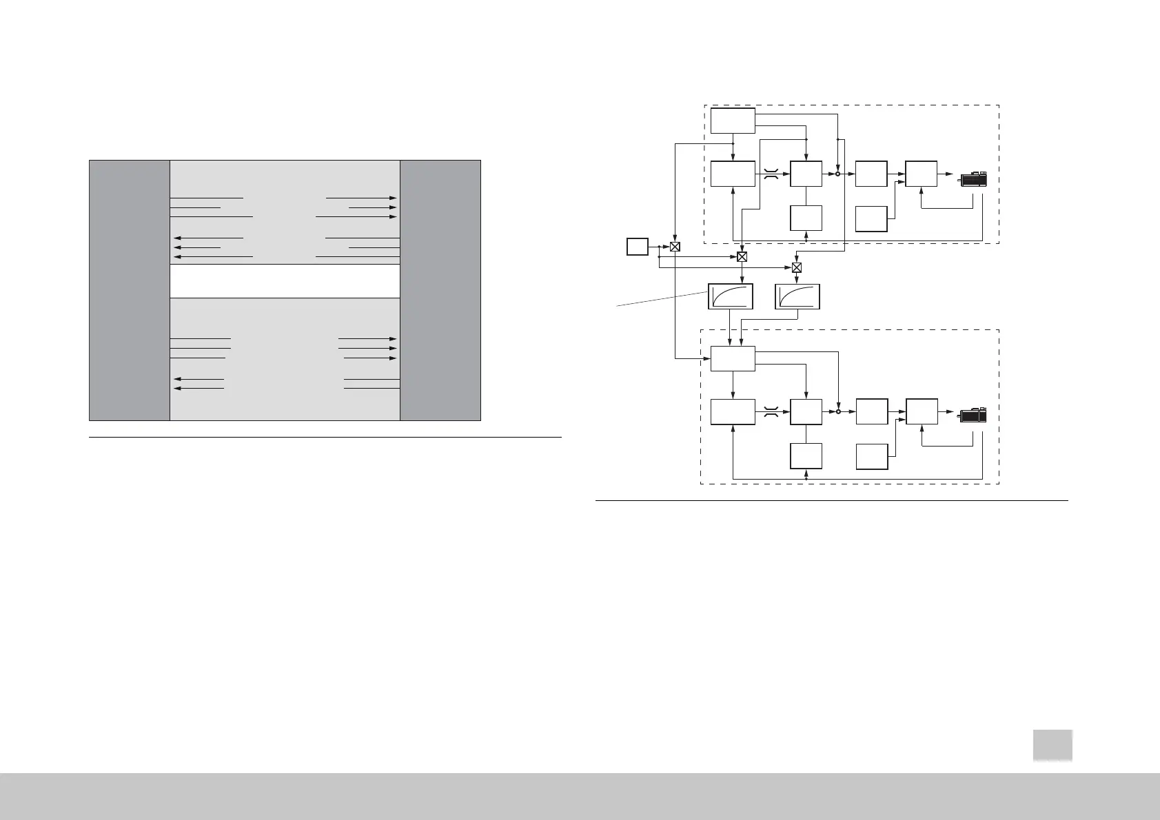
Figure 6.14: Gantry application control structure
P 2600
P 2272
P 2608
P 2587
P 0764
P 2607
P 2587
P 2604
P 2601
P 0281