Specification TWINsync module
35
6 TWINsync operation modes
ID no.: CB08759-001Date: 03/2023
moog
Static mapping
MSD
Slave
MSD
Master
Checksum
Communication state P2617
Torque setpoint P2596
Actual speed value P2599
Actual position value P4220
Error number P2650[0]
Control word P2611
Status word P2612
Mapping by operation mode
Virtual encoder VE (torque)
Error location P2650[1]
Checksum
Communication state P2617
Figure
6.10:
Process
data
interface
between
the
master
and
slave
drives
in
the
operation
mode:
"Virtual
Encoder
VE"
(torque)
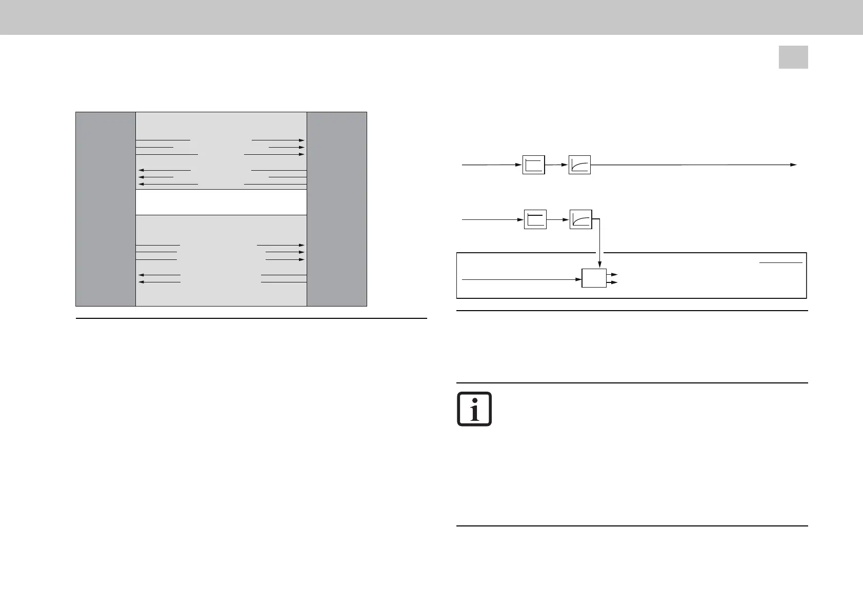
The following figure shows the control structure of the slave drive.
Receiving Master
Torque setpoint
P2603
Receiving Master
Actual speed value
P2606
Receiving Master
Actual position value
P4221
P2609[0]
32768
P2581
P2582
P2609[1]
32768
V
irtual encoder
Actual speed value, Slave
Actual position value, Slave (Single Turn)
Slave
Torque
setpoint
Encoder
CH3
Figure
6.11:
Virtual
encoder
VE
(torque)
control
structure
6.2.7 dSPACE TWINsync (rapid-prototyping
systems from the Fa. dSPACE company)
NOTE
The five operation modes
- PWM_SLAVE, 14
- TCON_SLAVE, 15
- SCON_SLAVE, 16
- PCON_1_SLAVE, 17
- PCON_2_SLAVE, 18
are described separately in the document: "TwinSync dSPACETwinSync
dSPACE - MSD Servo Drive"