Specification TWINsync module
24
6 TWINsync operation modes
ID no.: CB08759-001Date: 03/2023
moog
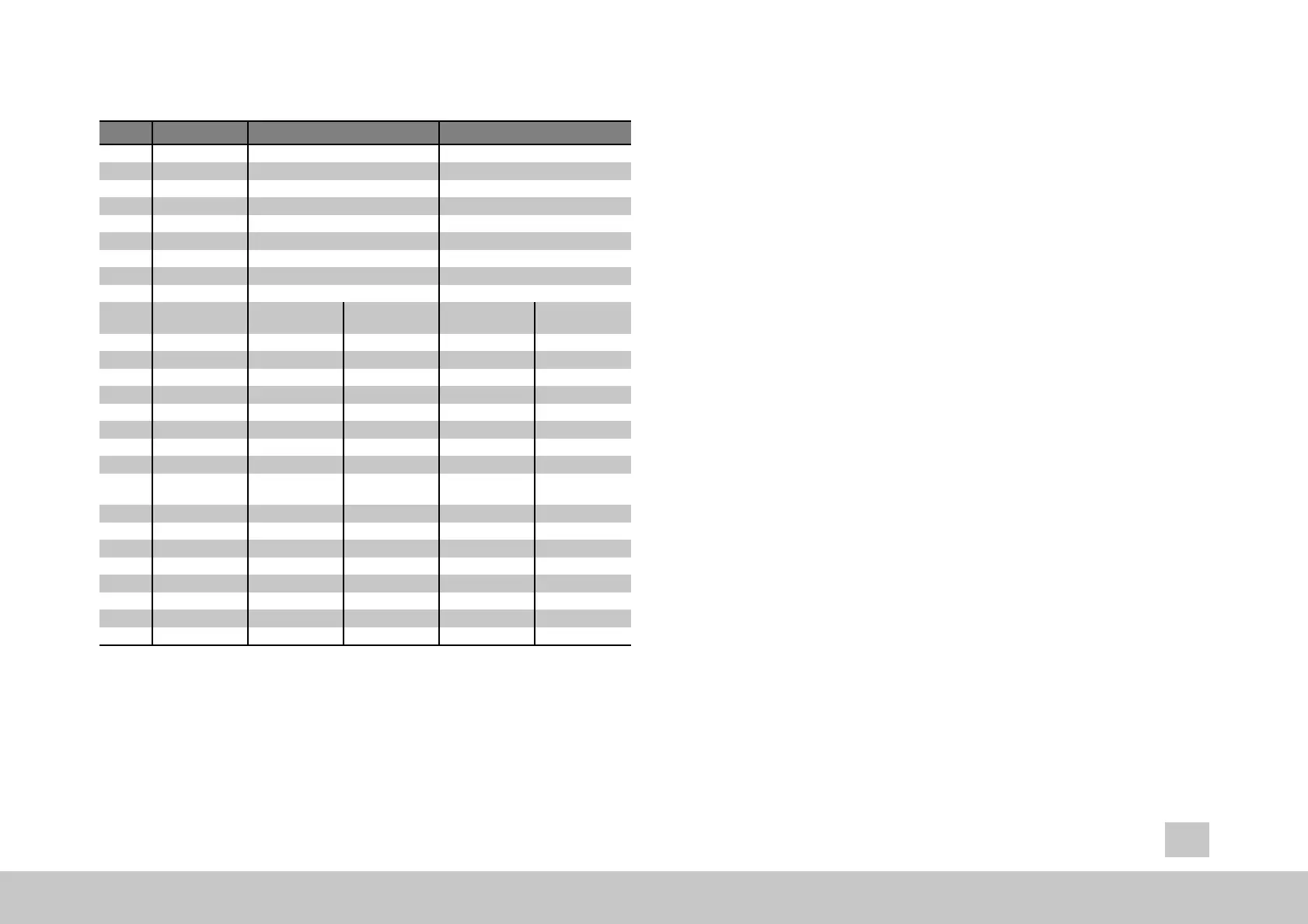
ID Parameters Setting in the master Setting in the slave
P2614 TWINdrive mode MASTER (2) SLAVE (1)
P2580 TWIN_Setting USER(0) USER(0)
P0300 Control mode - - - - - -
P0159 Control selector - - - - - -
P0165 Setpoint selector - - - - - -
P0301 Setpoint mode - - - - - -
P2584 Speed-up - - - - - -
P2602 Local scaling - - - - - -
P2609 Remote scaling - - - - - -
P2615 Mapping of the
sent data
Parameter value
(hex)
Meaning Parameter value
(hex)
Meaning
Sub-ID 0 0000.000x x objects (x = 0..7) 0000.000x x objects (x = 0..7)
Sub-ID 1 pppp.SSww 1. Object pppp.SSww 1. Object
Sub-ID 2 pppp.SSww 2. Object pppp.SSww 2. Object
Sub-ID 3 pppp.SSww 3. Object pppp.SSww 3. Object
Sub-ID 4 pppp.SSww 4. Object pppp.SSww 4. Object
Sub-ID 5 pppp.SSww 5. Object pppp.SSww 5. Object
Sub-ID 6 pppp.SSww 6. Object pppp.SSww 6. Object
Sub-ID 7 pppp.SSww 7. Object pppp.SSww 7. Object
P2616 Mapping of the
received data
Parameter value
(hex)
Meaning Parameter value
(hex)
Meaning
Sub-ID 0 0000.000x x objects (x = 0..7) 0000.000x x objects (x = 0..7)
Sub-ID 1 pppp.SSww 1. Object pppp.SSww 1. Object
Sub-ID 2 pppp.SSww 2. Object pppp.SSww 2. Object
Sub-ID 3 pppp.SSww 3. Object pppp.SSww 3. Object
Sub-ID 4 pppp.SSww 4. Object pppp.SSww 4. Object
Sub-ID 5 pppp.SSww 5. Object pppp.SSww 5. Object
Sub-ID 6 pppp.SSww 6. Object pppp.SSww 6. Object
Sub-ID 7 pppp.SSww 7. Object pppp.SSww 7. Object
Table 6.4: Parameters for the master and slave drives of the pre-set TWINsync
operation mode: User-specific mapping
pppp: Parameter ID in hex
SS: Parameter Sub-ID in hex
ww: 10 hex for 16 bit, 20 hex for 32 bit
6.2.2 TWin Drive profile “TWD”
(speed)
... with virtual encoder!
The "TWin Drive profile TWD" (speed) operation mode is suitable for speed
synchronization of mechanically coupled axes, for example, of travel or lift drives
with a double drive. The master sends its actual speed value and its actual torque
value to the TWINsync slave via the TWINsync interface. The TWINsync slave then
processes these two variables and passes them on to its internal control structure.
6.2.2.1 TWD_MASTER_V1 / TWD_SLAVE_V1, 1+2
This operation mode is selected by choosing P2580 = TWD_MASTER_V1 for the
master and P2580 = TWD_SLAVE_V1 for the slave. In this operating mode, the
master sends its torque actual
value (P2597) and its speed actual value (P2599) to
the slave. The received
data, which the master expects via TWINsync, are interpreted
as current error number (P2650[0]) and current error location (P2650[1]) of the slave
drive.
In this operating mode, the speed actual value of the master drive is used as th
e
main speed setpoint (main setpoint) of the slave drive. An additional setpoint value
is added to the main setpoint value which is proportional to the main setpoint value and
which is specified as a percentage of parameter P2584. If the additional setpoint value
calculated in this way goes below the threshold value specified in parameter P2585
(speed-up minimum), then this threshold value is used as the additional setpoint value.
The sign of the additional setpoint value corresponds to the sign of the torque actual
value of the master drive.