Specification TWINsync module
37
6 TWINsync operation modes
ID no.: CB08759-001Date: 03/2023
moog
ID Parameters Setting in the slave
P2609 Remote scaling
Setting in the master
- - - same as P2602 from master (for
speed)
P2615 Mapping of the sent
data
Parameter value
(hex)
Meaning Parameter value
(hex)
Meaning
Sub-ID 0 0000.0002 2 objects 0000.0001 1 object
Sub-ID 1 0A28.0020 local position
setpoint P2600 (32-
bit)
0A29.0020 local position
actual value
P2601 (32-bit)
Sub-ID 2 0A8E.0010 local speed setpoint
(LocalRefFFISpeed)
P2702 (16-bit)
Sub-ID 3
Sub-ID 4
Sub-ID 5
Sub-ID 6
Sub-ID 7
P2616 Mapping of the
received data
Parameter value
(hex)
Meaning Parameter value
(hex)
Meaning
Sub-ID 0 0000.0001 1 object 0000.0002 2 objects
Sub-ID 1 0A30.0010 RemoteActPos
P2608 (32-bit)
0A2F.0020 RemoteRefPos
P2607 (32-bit)
Sub-ID 2 0A2D.0010 RemoteRefSpeed
P2605 (16-bit)
Sub-ID 3
Sub-ID 4
Sub-ID 5
Sub-ID 6
Sub-ID 7
Table 6.11: Parameters for the master and slave drives of the pre-set TWINsync
operation mode: Position setpoint (position reference value) (continued)
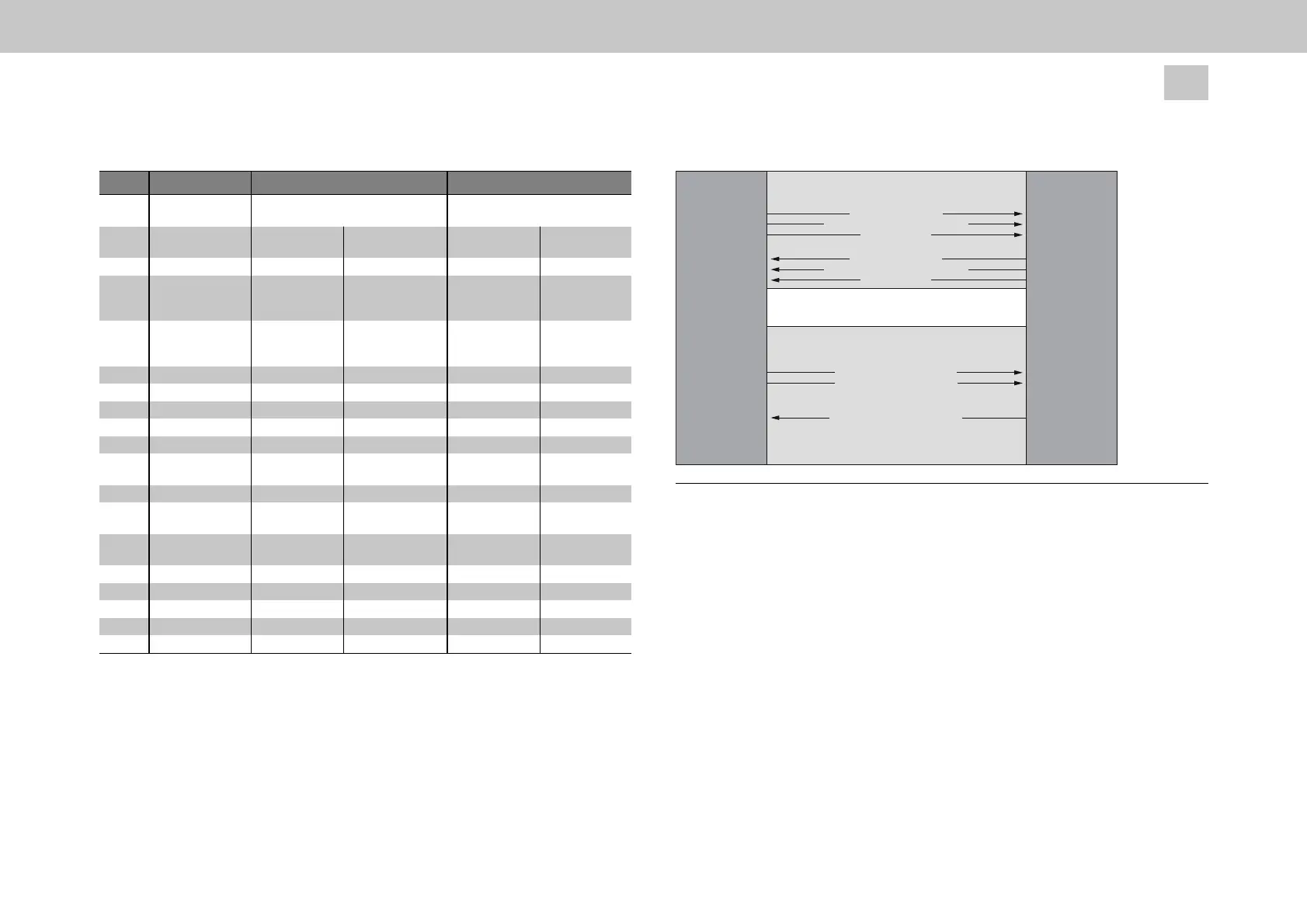
The following figure shows the process data interface between the master and slave
drives in the operation mode: Position setpoint (position reference value)
Static mapping
MSD
Slave
MSD
Master
Checksum
Communication state P2617
Position setpoint P2600
Speed setpoint P2702
Actual position value P2601
Control word P2611
Status word P2612
Mapping by operation mode
Position setpoint (position reference value)
Checksum
Communication state P2617
Figure
6.12:
Process
data
interface,
position
setpoint
(position
reference
value)
6.2.11 Serial Double Inverter "SDI" / Parallel Double
inverter "PDI"
This chapter describes a solution with which a combined operation of two servo drives
of the type G395-450/G397-450 on a single, common motor winding is possible. This
solution is intended for applications in which the maximum output current or the
maximum output power of one servo drives of the type G395-450/G397-450 is
inadequate.
The solution assumes the presence of a TWINsync communication connection
between the two inverters. One inverter is operated in master mode and is
parametrized in accordance with the application. The second inverter is operated in
slave mode and receives its control commands and setpoints from the master via the