Specification TWINsync module
20
5 Control via TWINsync
ID no.: CB08759-001Date: 03/2023
moog
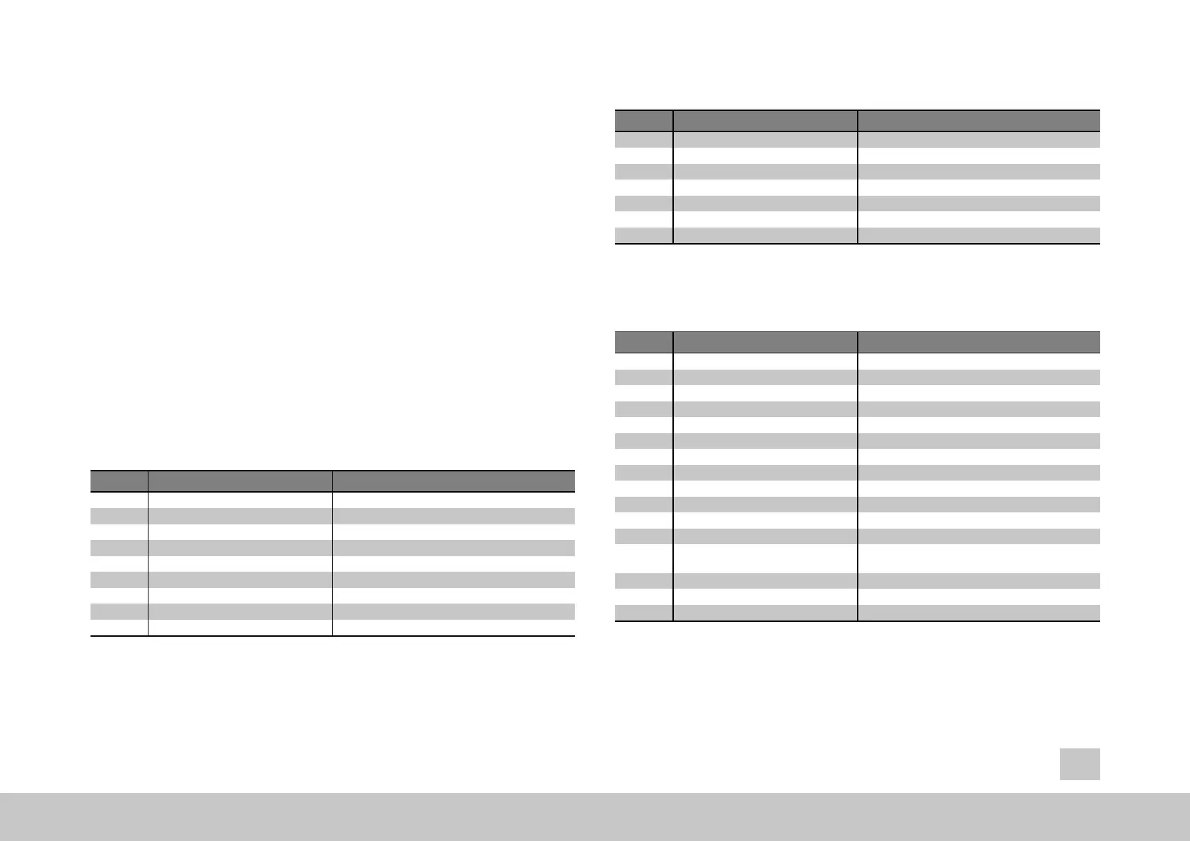
5 Control via TWINsync
The slave drive in the TWINsync set-up can be contro
lled by the TWINsync mast
er
via the TWINsync control word or via any other control location (e.g. digital inputs or
field bus). The control location can be configured via the control location selector
(P0159) MPRO_CTRL_SEL. To select the “TWINsync” as the control location, the
value TWIN(10) must be set for P0159. Control of the drive then takes place via the
TWINsync control word (parameter (P2611) MPRO_TWIN_SlaveCtrlWord, (see the
table for P2611) and the drive status is given in parameter (P2612) MPRO_TWIN_
SlaveStatus (see the table for P2612). The TWINsync master copies its own control
word onto the TWINsync control word that is sent from the TWINsync master to the
TWINsync slave via the process data channel. This causes the TWINsync slave to
obey the same control commands as the TWINsync master. In addition, error
acknowledgement and homing can be triggered on the slave via the TWINsync
control word. The TWINsync slave also sends its TWINsync status word back to the
TWINsync master via the process data channel.
Bit No. Function Description
0 Operation_mode_0
1 Operation_mode_1
2 Operation_mode_2
3 Operation_mode_3
4 Operation_mode_4
reserved
reserved
reserved
reserved
reserved
5 EnableOperation
6 SwitchOn
7 CoastStop
8 QuickStop
Begin control
Switch on the power stage
No torque applied to drive
Quick stop
Table 5.1: Structure of the TWINsync control word (P2611)
MPRO_TWIN_
SlaveCtrlWord
Bit No. Function Description
9 StartHoming
10 FaultReset
11 EnableVoltage
12 ReSyncPosition
13 FREE2
14 FREE3
15 FREE4
Start homing
Error reset
Enable power stage
Re-synchronization of the master position
reserved
reserved
reserved
Table 5.1: Structure of the TWINsync control word (P2611)
MPRO_TWIN_Sla-veCtrlWord (continued)
Bit No. Function Description
0 Operation_mode_0
1 Operation_mode_1
2 Operation_mode_2
3 Operation_mode_3
4 Operation_mode_4
reserved
reserved
reserved
reserved
reserved
5 OperationEnabled
6 Fault
7 Free_7
8 Free_8
9 HomePositionSet
10 Free_10
11 Free_11
12 OpInProgress
Control is active
Drive is in the error state
reserved
reserved
The drive has been homed
reserved
reserved
The slave is busy (is switching to the new DriveCom
state)
13 ActDrivecom_0
14 ActDrivecom_1
15 ActDrivecom_2
current DriveCom state bit 0
current DriveCom state bit 1
current DriveCom state bit 2
Table 5.2: Structure of the TWINsync status word (P2612) MPRO_TWIN_
SlaveStatus