Specification TWINsync module
31
6 TWINsync operation modes
ID no.: CB08759-001Date: 03/2023
moog
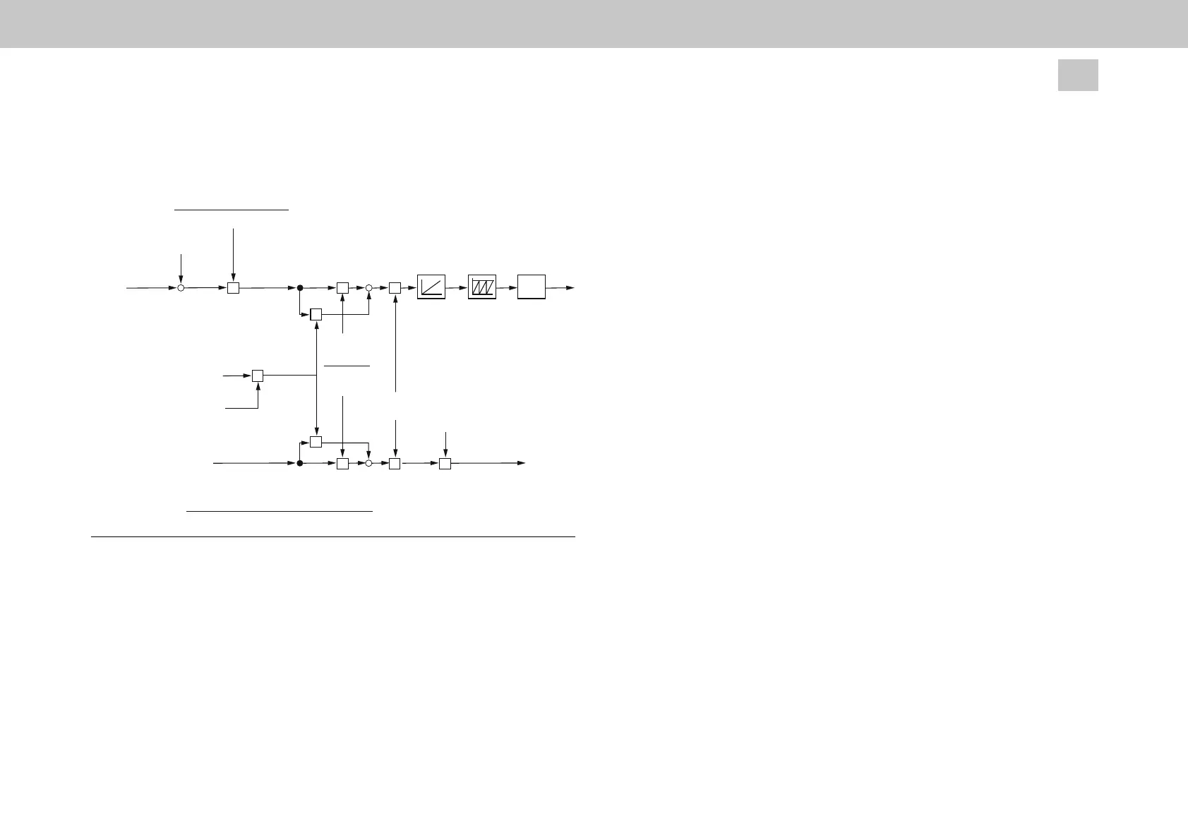
The following figure shows the control structure of the slave drive.
P2608
Master_ActualPosition (k)
∆ position
[incr]
∆ position_corr
[incr]
P2583
SlaveModuloValue
[incr]
Position setpoint
[Userunits]
according to standardisation
Correction factor_
Nref_FF
Speed_ForwardControlValue
[Userunits]
P2583
Slave_Inversion
[-1/1]
+
+
P2653
MPRO_TWIN_
ElecGearNum
P2654
MPRO_TWIN_
ElecGearDen
Analog input xx
[-1 ... 1]
P2655
Correction factor
P2606
Master_ActualSpeed
[rpm]
Master_ActualPosition
(k-1) [incr]
P270 Slave_Internal_Resolution
[incr/rev]
P2652 Master_Internal_Resolution
[incr/rev]
[incr]
-
POS 2
USER
x x
x
x
x
x x x
x
Slave_Internal_Resolution [Userunits/rev] * IpRefTS [ms]
CorrectionFactor_Nref_FF =
60000 [min * s/min * s/ms]
Figure
6.7:
Control
structure
for
position
control
(TWINpos)
About the position setpoint: Working from the incremental master actual position
P2608, delta increments are derived for each scanning step. If there is a difference in
the resolution factors between the master and slave, the delta increments are
corrected by the factor P0270 / P2652. Subsequently, the corrected delta increments
are multiplied first by the gear ratio of the electronic gear unit (
P2653 / P2654)
and
second
by the
analogue
correction
factor, and the results are
added.
Moreover, the
parameter P2583 can be used to realize a directional reversal between the master
and slave. Afterwards, the corrected delta increments are integrated to the modulo
value of the slave.
The current speed actual value of the master
i
n rpm i
s
u
sed for t
he external sp
e
e
d
pre-control.
Just as for the position processing, this actual value is multiplied by the
factor of the electronic gear unit (P0270 / P2652) as well as by the same analogue
correction factor.
6.2.4 Double inverter "DI"
The function “double inverter DI” includes operation modes 23 …
28, which are
described
separately
in a
document.
6.2.4.1 DI_MASTER, 9
The master operation mode 9 for the function “Double inverter DI” is no longer used
and is replaced by the corresponding master operation modes for serial and parallel
double inverters me
ntioned above.
6.2.5 Rack-and-Pinion Drive Control "RPDC"
Rack and Pinion Drive Control (RPDC) describes a method for controlling a gear
rack drive or planetary gear unit drive with two motors. The objective here is, on the
one hand, to create a tension between the two motors so that backlash present
between the gear wheels is compensated. On the other hand, the control is