Specification TWINsync module
12
4 Description of parameters
ID no.: CB08759-001Date: 03/2023
moog
4 Description of parameters
The specific parameters of the TWINsync option are described below.
NOTE:
A description of general parameters can be found in the MSD Servo Drive
Device Help.
4.1 General parameters of the TWINsync
communication interface
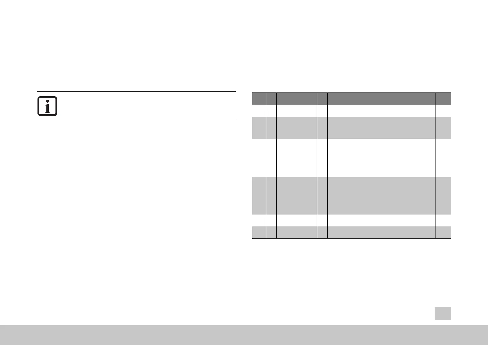
The following table shows the configuration parameters for the TWINsync
optioncommunication interface.
ID
Sub
ID
Name Unit Description
Data
type
P
2613
TOPT_TWIN_
MaxFaultTime
ms Maximum communication fault time (timeout monitoring) Float32
P
2614
TOPT_TWIN_Mode wet Select Master or Slave Mode
0 = OFF
1 = SLAVE
2 = MASTER
UInt16
P
2615
0-7 TOPT_TWIN_
ProcessSendData
Mapping of process data to be sent (TX data)
Sub-ID:
0: Number of mapped process data or 1st mapped object
(only extended mapping)
1-7: mapped objects (see standard mapping or extended
mapping)
UInt32
P
2616
0-7
TOPT_TWIN_
ProcessReceiveData
UInt32
P
2617
TOPT_TWIN_
Statusword (ro)
bits
Mapping of process data to be sent (RX data)
Sub-ID:
0: Number of mapped process data or 1st mapped object
(only extended mapping)
1-7: mapped objects (see standard mapping or extended
mapping)
Received system status word UInt16
P
2618
TOPT_TWIN_
SyncTicks
Max. synchronization ticks with 15ns/tick. This means the
gain of the synchronization controller.
Int16
Table 4.1: Configuration parameters of the TWINsync technology option card