SpecificationTWINsync module
15
4 Description of parameters
ID no.: CB08759-001Date: 03/2023
moog
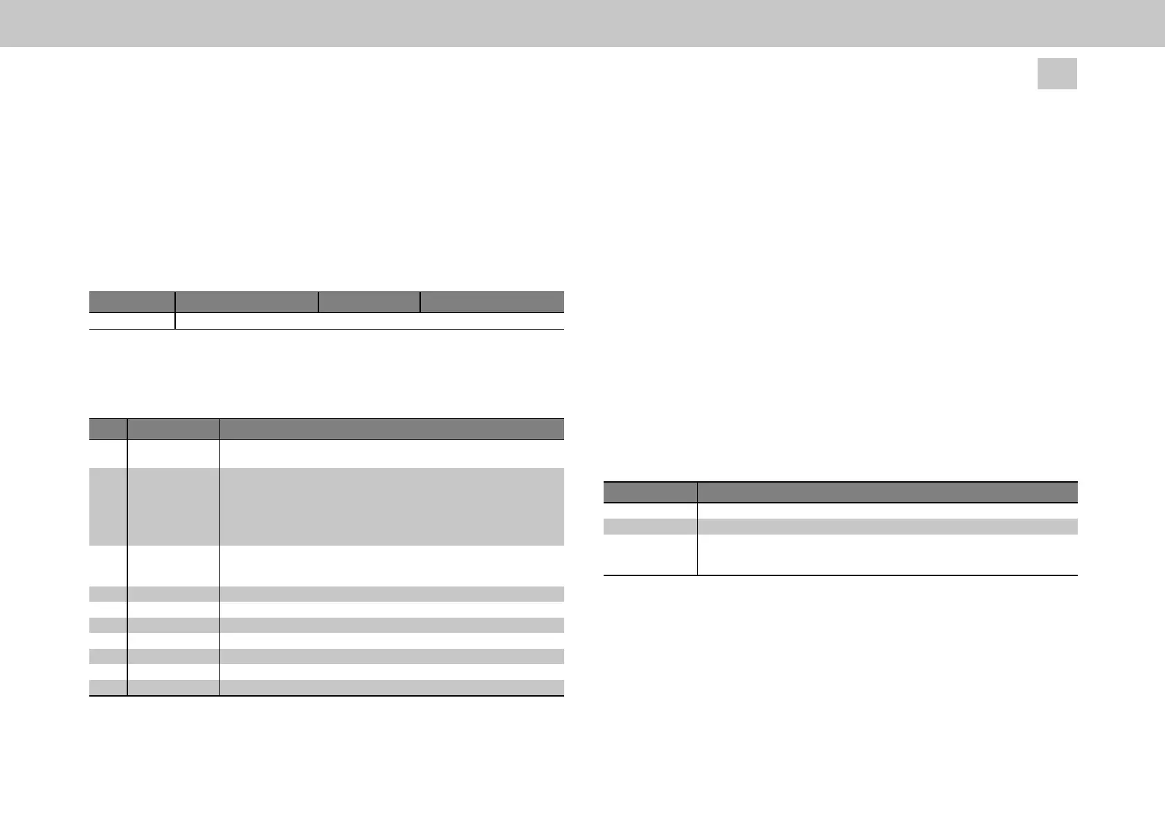
The extended-mapping mode can be selected with parameter (P2580) MPRO_
TWIN_Setting = EXT_MAP_MASTER(31) or EXT_MAP_SLAVE(32). In this case, the
TWINsync
d
ata telegram i
s
st
ructured as sh
o
w
n i
n t
h
e n
e
xt
t
able: It consists of 2
bytes of fixed data (16-bit CRC) again followed by a variable number of bytes of
process data. The TWINsync data telegram example in the table is shown with 14
bytes for PDO data for a total frame length of 16 bytes. This is accomplished with the
setting parameter Framesize = 0 (== (P2709) TOPT_TWIN_PhyLinkConfig[1]).
Checksum (fixed) PDO1 (configurable) ... PDOn (configurable)
2 bytes 14 bytes
Table 4.4: TWINsync data telegram (extended mapping)
The checksum is derived using the entire telegram. The structure of the TWINsync
status word (
P2617)
TOPT_TWIN_Statusword) is
shown in
the following table.
Bit No. Function Description
0 ProcessData Mode 0 = Initialization mode
1 = cyclical mode
1-3 SwitchingFrequency 000 = 2 kHz
001 = 4 kHz
010 = 6 kHz
011 = 8 kHz
100 = 12 kHz
101 = 16 kHz
4-5 TWINMode 00 = TWINsync off
01 = TWINsync Slave
10 = TWINsync Master
6 not_used reserved
7-10 DRVCOMstate current state of DriveCom
11 ChopperState current chopper state
12 PWM_Period 'pwm is counting down'
13 PWMDisableEv 'pwm disable event'
14 SystemError Drive in the “error” state
15 TechOptError A communication error is pending
Table 4.5: Structure of the received TWINsync status word (parameter P2617)
The definition of the freely configurable data is described below.
3.1.4 Configuration of the process data in the standard-
mapping mode
The process data which is to be sent and received by the drive can be configured by
means of parameters. For a manual
configuration, the parameters (
P2615)
TOPT_
TWIN_ProcessSendData (mapping of the sent data) and
(
P2616
) TOPT_TWIN_
P
ro
ce
ssR
e
ce
i
veData (mapping of the received data) can be modified directly. An
automatic configuration for pre-set operation modes is also possible via the operation
mode selector (P2580) MPTO_TWIN_Setting (see chapter "TWINsync operation
modes" on page 19). The parameters P2615 / P2616 are each field parameters with 8
elements. The first element (SubID: 0) specifies how many parameters are sent/
received by this axis. A maximum of 7 parameters in each direction are supported. The
other field elements (SubID:1-7) determine which parameters are sent/received. The
entries under SubID 1-7 are coded as described in the following table.
Bit field Meaning, SubID 1..7 (standard-mapping mode)
PPPPxxxxh 2-byte parameter ID of the parameter that is to be sent as a HEX value
xxxxSSxxh 1-byte parameter Sub-ID of the parameter that is to be sent as a HEX value
xxxxxxWWh 1-byte word width of the parameter which is to be sent as a HEX value
32-bit parameter (Int32,UInt32, Float32): WW =20h
16-bit parameter (Int16,UInt16): WW = 10h
Table 4.6: Structure of parameters P2615 / P2616 (Sub-Id: 1-7) for mapping the
process data which is to be
sent in the standard-mapping mode
When configuring the process
d
ata, i
t i
s
e
ssential to be sure that t
h
e se
q
u
e
n
ce
a
nd
the data width of the received data of the one axis match the sequence and the data
width of the sent data of the other axis. This matching of the parametrization cannot
be monitored by MSD Servo Drive and must therefore be ensured by the user.