Specification TWINsync module
39
6 TWINsync operation modes
ID no.: CB08759-001Date: 03/2023
moog
6.2.12 Gantry application
Operation mode for gantry applications with position and speed tacking error
monitoring. Suitable for all control modes.
In contrast to operation modes 21 and 22, the actual position is always sent. The
speed and torque sent are determined directly from the feed forward control values
of the master and could also be used in the slave as feed forward control values
(minimization of the tracking error).
Operation modes 29 and 30 also differ f
rom 21 and 22 in the monitoring of the slave
position and speed. The master monitors these values in operation mode 29
(position tracking error from P-744 and speed tracking error from P-2595). If there is a
deviation, ERR-39 is generated.
6.2.12.1 PCON_GANTRY_MASTER / PCON_GANTRY_
SLAVE, 29+30
This operation mode is selected by choosing P2580 = PCON_GANTRY_MASTER
for the master and P2580 = PCON_GANTRY_SLAVE for the slave.
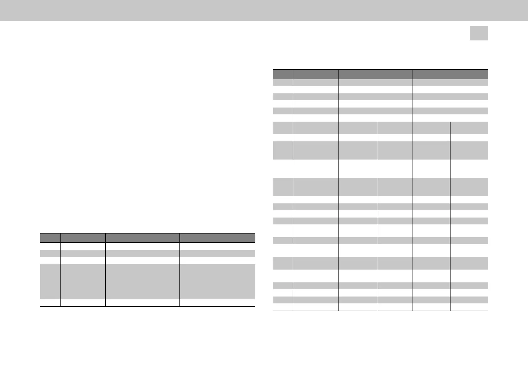
ID Parameters Setting in the master Setting in the slave
P2614 SLAVE (1)
P2580 PCON_GANTRY_SLAVE(30)
P0300 same as P0300 from master
P2701
TWINdrive mode
TWIN_Setting
Control mode
Slave synchronization
MASTER (2)
PCON_GANTRY_MASTER(29)
same as P0300 from slave
- - - 0 = SLAVE_SYNC_ISR, TwinSlave:
Synchronization via TWIN (Mode 1)
1 = SLAVE_SYNC_COM, TwinSlave:
Synchronization via field bus
2 = SLAVE_SYNC_ENC, TwinSlave:
Synchronization via TWIN (Mode2)
P0159 Control selector any TWINSYNC(10)
Table 6.14: Parameters for the master and slave drives of the pre-set TWINsync
operation mode: Gantry a
pplication
ID Parameters Setting in the master Setting in the slave
P0165 Setpoint selector
P0301 Setpoint mode
P2584 Speed-up
P2602 Local scaling
P2609 Remote scaling
P2583 SlaveInverted
any
any
- - -
any
same as P2602 from slave
1 / -1
TWINSYNC(11)
IP-Mode(1)
- - -
any
same as P2602 from master
1 / -1
P2615 Mapping of the sent
data
Parameter value
(hex)
Meaning Parameter value
(hex)
Meaning
Sub-ID 0 0000.0003 3 objects 0000.0002 2 objects
Sub-ID 1 0A28.0020 local position
setpoint P2600
(32-bit)
0A29.0020 local position
actual value
P2601 (32-bit)
Sub-ID 2 02FC.0020 spec. speed
setpoint P0764
(32-bit)
0119.0020 spec. speed
actual value
P0281 (32-bit)
Sub-ID 3 08E0.0010 spec. torque
actual value
P2272 (16-bit)
Sub-ID 4
Sub-ID 5
Sub-ID 6
Sub-ID 7
P2616 Mapping of the
received data
Parameter value
(hex)
Meaning Parameter value
(hex)
Meaning
Sub-ID 0 0000.0002 2 objects 0000.0003 3 objects
Sub-ID 1 0A30.0020 RemoteActPos
P2608 (32-bit)
0A2F.0020 RemoteRefPos
P2607 (32-bit)
Sub-ID 2 0A1B.0020 ActSpeedMaster
P2587 (32 bit)
0A1B.0020 ActSpeedMaster
P2587 (32 bit)
Sub-ID 3 0A2C.0010 RemoteActTorque
P2604 (16-bit)
Sub-ID 4
Sub-ID 5
Sub-ID 6
Sub-ID 7
Table 6.14: Parameters for the master and slave drives of the pre-set TWINsync
operation mode: Gantry a
pplication (continued)