Specification TWINsync module
38
6 TWINsync operation modes
ID no.: CB08759-001Date: 03/2023
moog
TWINsync interface. The slave sends actual values and status information to the
master via the TWINsync interface. The slave is operated either with direct
specification of the PWM duty cycles or in current-controlled mode.
6.2.11.1 TWINsync dual inverter operation modes
In the dual inverter operation mode, two inverters operate in master-slave mode.
Both inverters are connected to a common motor winding on the output side. In this
case, for the slave inverter, a distinction is made between the control modes “PWM
mode” and “ICON mode”. In the PWM mode, the master sends the PWM switching
times directly to the slave. In the ICON mode, the d and q current setpoints as well as
the commutation angle measured by the master are sent from the master to the
slave. The slave the operates with a field-oriented current control without its own
encoder evaluation. The outputs of the master and slave can be connected in
parallel or in series in this case.
The following table describes the new TWINsync operation modes which can be set
via the parameter P2580 (MPRO_TWIN_Setting).
ID Value Selection text
Description
P2580 23 MPRO_TWIN_SDI_
Master_PWM
Serial dual inverter master (slave in PWM mode)
24 MPRO_TWIN_PDI_
Master_PWM
Parallel dual inverter master (slave in PWM mode)
25 MPRO_TWIN_SPDI_
Slave_PWM
Serial/parallel dual inverter slave (slave in PWM mode)
26 MPRO_TWIN_SDI_
Master_ICON
Serial dual inverter master (slave in ICON mode)
(not yet selectable)
27 MPRO_TWIN_PDI_
Master_ICON
Parallel dual inverter master (slave in ICON mode)
(not yet selectable)
28 MPRO_TWIN_SPDI_
Slave_ICON
Serial/parallel dual inverter slave (slave in ICON mode)
(not yet selectable)
Table 6.12: TWINsync operation modes for dual inverter operation
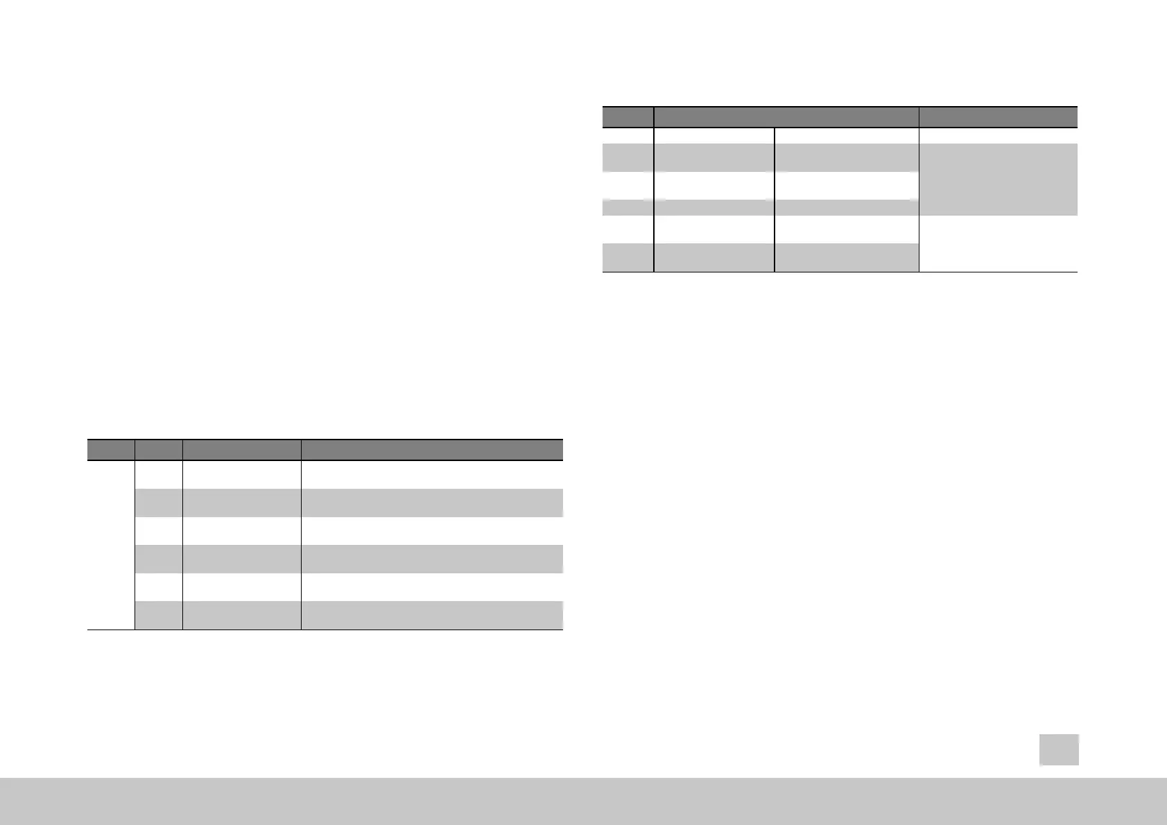
No. Operation mode combinations
Wiring
P2580 (master) P2580 (slave)
1 MPRO_TWIN_SDI_
Master_ICON
MPRO_TWIN_SPDI_Slave_
ICON
Inverters wired in series to a
motor winding open on both sides
2 MPRO_TWIN_SDI_
Master_PWM
MPRO_TWIN_SPDI_Slave_
PWM
3 MPRO_TWIN_PDI_
Master_ICON
MPRO_TWIN_SPDI_Slave_
ICON
Inverters wired in parallel to a
standard motor winding
with balance coils to provide
isolation
4 MPRO_TWIN_PDI_
Master_PWM
MPRO_TWIN_SPDI_Slave_
PWM
Table 6.13: Useful combinations of TWINsync operation modes in dual-inverter
operation
Because this concerns rather “exotic” applications, the responsible field or global
application engineer should be consulted, possibly also with assistance from the
development department.
6.2.11.2 Operation modes 23, 24, 25, 26, 27 and 28
The operation modes
l
l
l
l
l
l
SDI_PWM_MASTER (pwm mode), 23
PDI_PWM_MASTER (pwm mode), 24
SDI_PDI_PWM_SLAVE (pwm mode), 25
SDI_CURR_MASTER (current mode), 26
PDI_CURR_MASTER (current mode), 27
SDI_PDI_CURR_SLAVE (current mode), 28
are described again separately with wiring diagrams, start-up information and
related documentation in a seperate document.