Specification TWINsync module
14
4 Description of parameters
ID no.: CB08759-001Date: 03/2023
moog
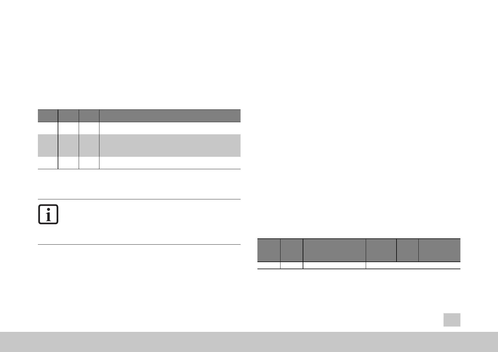
4.1.1 Master/Slave Selector (P 2614) TOPT_TWIN_
Mode
The TWINsync slave synchronizes wi
th the TWINsync master via the TWINsync
interface. This means that one of the drives must be parametrised as the TWINsync
master and one as the TWINsync slave. The parameter (P2614) TOPT_TWIN_Mode
is for defining the master/slave operation mode.
ID
Selection
text
Value Description
P 2614 OFF 0 The selection OFF disables the TWINsync interface. In the OFF state, no
process data are sent and no SYNC OUT signal is generated.
SLAVE 1
The selection SLAVE puts the MSD Servo Drive into the TWINsync slave
mode. The slave drive synchronizes its controller cycle with the incoming
SYNC
IN signals. If the SYNC IN signal remains absent for a configurable
time, a communication error is reported (see the next section).
MASTER 2
The selection MASTER puts the MSD Servo Drive into the TWINsync master
mode. SYNC OUT signals are generated for the slave.
Table 4.2: Setting options for (P2614) TOPT_TWIN_Mode
NOTE:
It is mandatory for the synchronization that both dri
ves be set for the same
switching frequency because this is used for the synchronization. This
means that the parameter (P0302) CON_SwitchFreq must be set to the
same value for both axes.
4.1.2 Timeout monitoring for the communication
A communication interface fault is recognized as follows:
l The MSD Servo Drive receives invalid data (CRC monitoring)
l The TWINsync master synchronization signal is not sent.
If one of these error occurs, it is assumed that the transmission channel is
malfunctioning. The parameter (P2613) TOPT_TWIN_MaxFaultTime specifies for
w
hat time interval (in ms) the channel can be considered to be malfunctioning
without an error being reported. This monitoring is not enabled in the extended
mapping mode. The monitoring of valid frames can be performed in this use case
with the corresponding scope signals, for example in the MSD PLC. If there is a fault,
the last correctly received data are frozen. The error messages are documented in
the chapter " Monitoring functions / Error messages" on page 41.
For commissioning, it is therefore recommended that ma
ster and slave be
configured and then an initialization be forced, or a restart of the devices be carried
out (P0149) MPRO_DRVCOM_Init). It is possible to check for valid or invalid
communication by means of scope variables ID-5709 (TWIN_FrameValid) or ID-
5710 (TWIN_FrameErrorCounter).
4.1.3 Structure of a TWINsync data telegram
A TWINsync data telegram in the standard-mapping mode is structured
as shown in
the table below. It consists of 3x2 bytes of fixed data (16-bit CRC, 16-bit TWINsync
status word and a control word or status word for changing the slave device state)
followed by a variable number of bytes of process data, or PDOs (process data
objects). The TWINsync data telegram example in the table is shown with 10 bytes
for PDO data for a total frame length of 16 bytes. This is accomplished with the setting
parameter Framesize = 0 (== (P2709) TOPT_TWIN_PhyLinkConfig[1]).
Checksum
(fixed)
TWINsync
status
word
(fixed)
PDO1 (con-
figurable)
...
PDOn (con-
figurable)
2 bytes 2 bytes
Control or status word
(DRIVECOM) (fixed)
2 bytes 10 bytes
Table 4.3: TWINsync data telegram (standard mapping)