Troubleshooting Charts: RX RF Failure 5-43
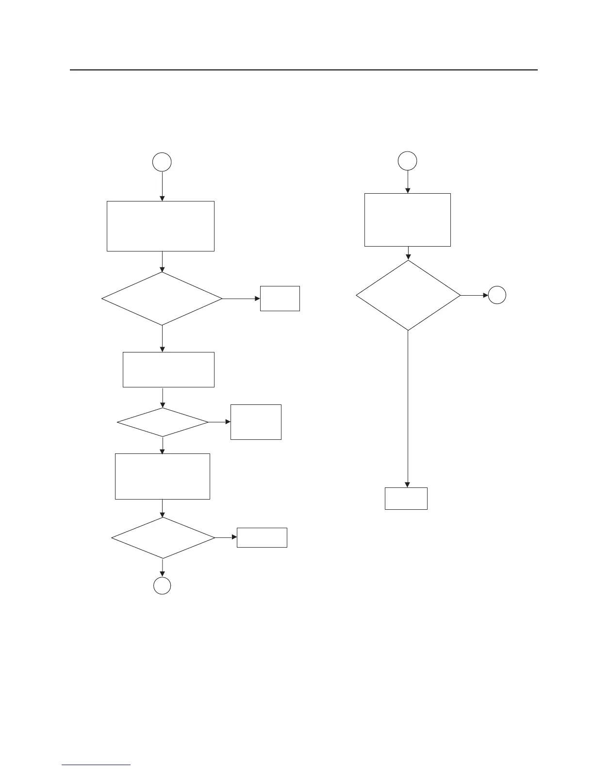
RX RF Failure – Page 10
Check Mixer:
Remove shield, SH4. Check the
polarity of T506 and check to
see that all pins are grounded.
Visually inspect windings.
Is the polarity
correct and all pins
are gounded?
13
Remove shield, SH10.
Measure the LO Power going
into the Mixer, U507 at the
output side of R525.
Check the polarity of T507
and check to see that all
pins are grounded. Visually
inspect windings.
Is the polarity
correct and all pins
are gounded?
Replace
T506
No
Yes
Replace T507
Check FGU
and replace
U507 if needed
8
Remove shields, SH2 &
SH10. Measure IF level at
XTAL filter and compute
XTAL filter loss, non
ground side of C515 and
non ground side of C644.
Loss:
No problem
found.
12
No
Yes
8
Yes
Note: RF Test frequency used:
VHF: 154.275MHz
UHF1: 424.975MHz
UHF2: 485.075MHz
700: 769.0625MHz
800: 860.0625MHz
900: 938.0625MHz
Measured with a High Frequency Probe for
relative comparisons and troubleshooting only.
Actual S21 gain or loss may differ if the
test point is not 50 ohms.
Is the LO power
= -3 dBm?
Yes
No
No
700 < 5.5 dB?
800 < 5 dB?
900 < 5 dB?
VHF/UHF1/UHF2 < 5 dB?
 Loading...