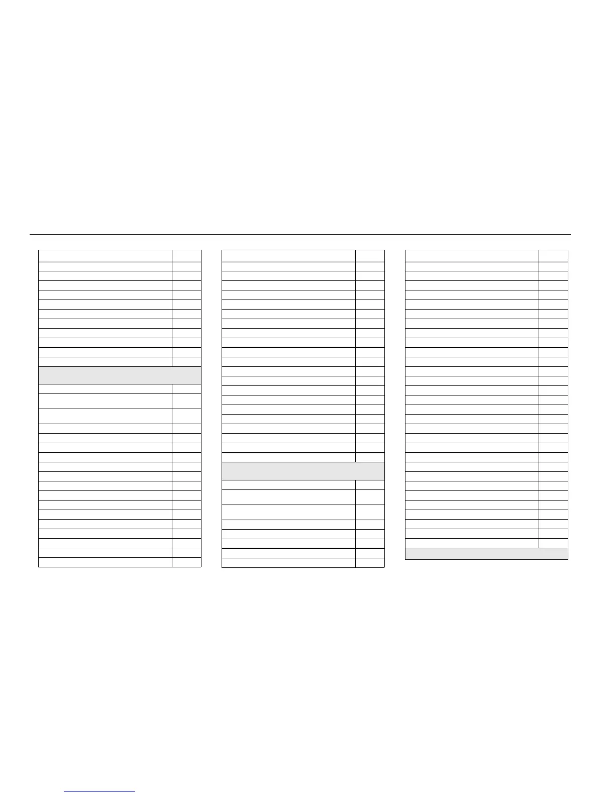
8-2 Schematics, Boards Overlays, and Parts Lists: List of Transceiver Schematics and Board Overlays
Display/Keypad Lighting Control Circuit (84012313002) 8-135
Display/Keypad Lighting Control Circuit (PC000353A01) 8-136
LCD and Keypad Connector Circuit (84012313002) 8-137
LCD and Keypad Connector Circuit (PC000353A01) 8-138
GCAI MACE BT Interconnect Circuit (84012313002) 8-139
GCAI MACE BT Interconnect Circuit (PC000353A01) 8-140
GPS Bluetooth Circuit 8-141
Transceiver (RF) Board Layout – Top Side (84012313002) 8-142
Transceiver (RF) Board Layout – Bottom Side (84012313002) 8-143
Transceiver (RF) Board Layout – Top Side (PC000353A01) 8-144
Transceiver (RF) Board Layout – Bottom Side (PC000353A01) 8-145
UHF2: 84012432001 (APX 2000/ APX 4000/ APX 4000Li) /
PC000354A01 (APX 2000/ APX 4000 (Two Knobs))/
Transceiver (RF) Mainboard Overall Schematic (84012432001) 8-185
Transceiver (RF) Mainboard Overall Schematic (PC000354A01)
– 1 of 2
8-186
Transceiver (RF) Mainboard Overall Schematic (PC000354A01)
– 2 of 2
8-187
Controller Mainboard Circuit 8-188
DC Circuit 8-189
Transmitter HF Circuit 8-190
Power Amplifier Circuit 8-191
Automatic Level Control Circuit 8-192
Receiver Front End Circuit 8-193
Receiver Back End Circuit – 1 of 2 8-194
Receiver Back End Circuit – 2 of 2 8-195
Receiver VCO Circuit 8-196
Transmitter VCO Circuit 8-197
Frequency Generation Unit Circuit – 1 of 2 8-198
Frequency Generation Unit Circuit – 2 of 2 8-199
DC Circuit 8-200
RF Interconnects Circuit 8-201
CPLD Circuit 8-202
Table 8-1. List of Transceiver Schematics and Board Overlays (Continued)
Transceiver Board Schematic/Board Layout Page No.
OMAP User Interface Circuit 8-203
Memory Interface Circuit (84012432001) 8-204
Memory Interface Circuit (PC000354A01) 8-205
Audio Circuit (84012432001) 8-206
Audio Circuit (PC000354A01) 8-207
MAKO/DC Distribution Circuit (84012432001) 8-208
MAKO/DC Distribution Circuit (PC000354A01) 8-209
Serial Interface Circuit 8-210
GPS Bluetooth Circuit 8-211
Controller Circuit (84012432001) 8-212
Controller Circuit (PC000354A01) 8-213
Display/Keypad Lighting Control Circuit (84012432001) 8-214
Display/Keypad Lighting Control Circuit (PC000354A01) 8-215
LCD and Keypad Connector Circuit (84012432001) 8-216
LCD and Keypad Connector Circuit (PC000354A01) 8-217
GCAI MACE BT Interconnect Circuit (84012432001) 8-218
GCAI MACE BT Interconnect Circuit (PC000354A01) 8-219
Transceiver (RF) Board Layout – Top Side (84012432001) 8-220
Transceiver (RF) Board Layout – Bottom Side (84012432001) 8-221
Transceiver (RF) Board Layout – Top Side (PC000354A01) 8-222
Transceiver (RF) Board Layout – Bottom Side (PC000354A01) 8-223
700/800 MHz : 84012266001 (APX 2000/ APX 4000/ APX 4000Li) /
PC000351A01 (APX 2000/ APX 4000 (Two Knobs))
Transceiver (RF) Board Overall Schematic (84012266001) 8-263
Transceiver (RF) Board Overall Schematic (PC000351A01) – 1
of 2
8-264
Transceiver (RF) Board Overall Schematic (PC000351A01) – 2
of 2
8-265
Controller Mainboard Circuit 8-266
DC Circuit 8-267
Receiver Back End Circuit 8-268
Receiver Front End Circuit 8-269
ANTSWI Circuit 8-270
Table 8-1. List of Transceiver Schematics and Board Overlays (Continued)
Transceiver Board Schematic/Board Layout Page No.
Automatic Level Control Circuit 8-271
Receiver Back End Circuit 8-272
Frequency Generation Unit Circuit – 1 of 2 8-273
Frequency Generation Unit Circuit – 2 of 2 8-274
Power AmplifierCircuit 8-275
Transmitter HF Circuit 8-276
VCO Circuit 8-277
CPLD Circuit 8-278
OMAP User Interface Circuit 8-279
Memory Interface Circuit (84012266001) 8-280
Memory Interface Circuit (PC000351A01) 8-281
Audio Circuit (84012266001) 8-282
Audio Circuit (PC000351A01) 8-283
MAKO/DC Distribution Circuit (84012266001) 8-284
MAKO/DC Distribution Circuit (PC000351A01) 8-285
Serial Interface Circuit 8-286
RF Interconnects Circuit 8-287
Controller Circuit (84012266001) 8-288
Controller Circuit (PC000351A01) 8-289
Display/Keypad Lighting Control Circuit (84012266001) 8-290
Display/Keypad Lighting Control Circuit (PC000351A01) 8-291
LCD and Keypad Connector Circuit (84012266001) 8-292
LCD and Keypad Connector Circuit (PC000351A01) 8-293
GCAI MACE BT Interconnect Circuit (84012266001) 8-294
GCAI MACE BT Interconnect Circuit (PC000351A01) 8-295
GPS Bluetooth Circuit 8-296
Transceiver (RF) Board Layout – Top Side (84012266001) 8-297
Transceiver (RF) Board Layout – Bottom Side (84012266001) 8-298
Transceiver (RF) Board Layout – Top Side(PC000351A01) 8-299
Transceiver (RF) Board Layout – Bottom Side (PC000351A01) 8-300
900 MHz : 84012478001
Table 8-1. List of Transceiver Schematics and Board Overlays (Continued)
Transceiver Board Schematic/Board Layout Page No.

 Loading...


