7-46 Troubleshooting Tables: List of Board and IC Signals
7.1.3 APX 2000/ APX 4000/ APX 4000Li and APX 2000/ APX 4000 (Two Knobs)
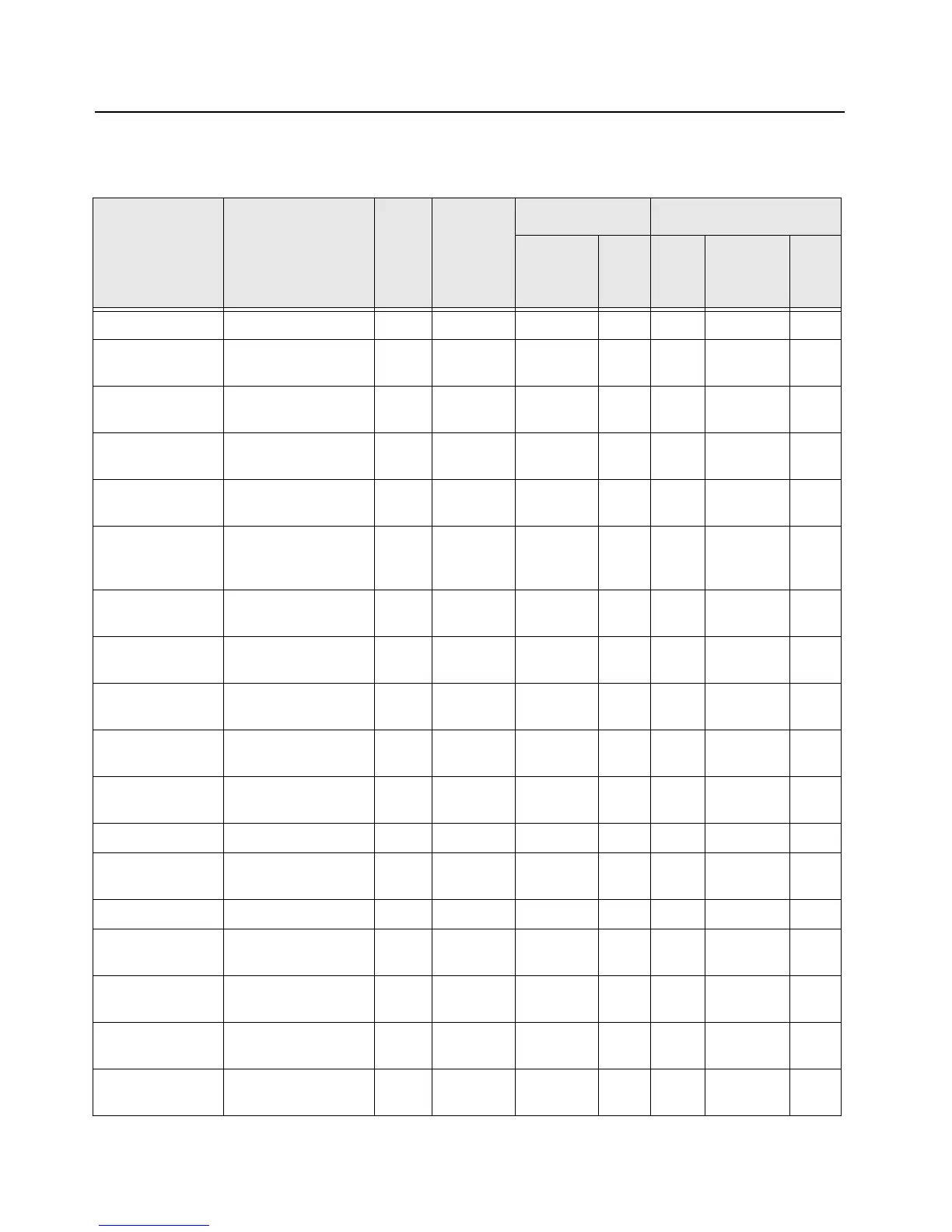
Table 7-18. Overall GPIO pin functions
Signal Name Description
Pin
or
Ball #
Active
State
SW Initialized HW Reset
Direction
*
PU State Direction
*
PU
or
PD
NC NC M8 Output 0 Output
codec_cs DSP SPI chip select
for TI dual CODEC
Y1 0 Output 1 Output
abacus_cs DSP SPI chipselect
for Abacus IC
L3 0 Output 0 Output
trident_cs DSP SPI chipselect
for Trident IC
V6 0 Output 0 Output
synthesizer_lock RF synthesizer lock
detect
V15 1=Lock Input None Input None
f2_timer_dmcs Timer output com-
pare for DMCS or
SYNCB
M20 1 Output Input Pull-
down
mako_tx_rx Trigger for Mako DAC
ramp
L14 1=TX Output *Input None
On_Off_Switch** Radio On_Off detec-
tion
G19 0 Output 0 Output
option_spi_cs Option board SPI
chip select
W9 0 Output 0 Output
dac_cs RF DAC chip select T19 0 Output Input Pull-
down
push_to_talk Push to talk button
input
T20 0 Input None Input Pull-
down
mako_intx Mako main interrupt P15 0 Input None Input None
mako_usb_intx Mako USB interrupt AA9 0 Input None Input Pull-
down
mako_option_intx Mako Option interrupt Y12 0 Input None Input None
Unused and Unwired
OMAP Pin
M14 Input Pull-
down
Input Pull-
down
top_display_cs Top LCD SPI chip
select
P3 0 Output 1 Output
Unused and Unwired
OMAP Pin
V19 Output 0 Output
mako_cs Mako IC SPI chip
select
N15 1 Output Input Pull-
down

 Loading...


