3-32 Theory of Operation: Controller
3.2.3 Clock Sources
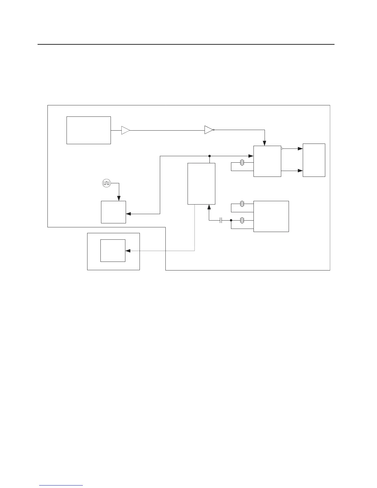
The main board and keypad board contains multiple crystal clock sources. These sources are active
upon power-up. The controller receives a 16.8 MHz sine wave from the RF section, which is shaped
into square wave and fed to the OMAP timer input. Screen shots and test points for these clock
signals are shown in Chapter 6.
Figure 3-23. Controller Clock Architecture
GPS
26 MHz
OMAP
MAKO
CPLD
DDR
SQUARING
TRIDENT
24.576 MHz
32.768 kHz
12 MHz
4.096 MHz
32.768 kHz
16.8 MHz
96 MHz
MACE
Keypad Board
Main Board

 Loading...


