3-2 Theory of Operation:
- APX 2000/ APX 4000 (Two Knobs): Contains an On/Off & Volume Knob, a 16 position
Channel/Frequency Knob, a push button switch used for Emergency call and a light bar.
The top control also includes TX/RX LED that is solid amber upon receive, red on PTT, and
blinks amber on secure TX/RX.
• Main Display – 160 x 90 TFT transflective color LCD.
•Keypad
- Standard Control (M1.5) Keypad version has 3 soft keys
- Limited Keypad Version has 3 soft keys, 4 direction Navigation key, Home and Data but-
tons
• Full Keypad Version has 3 soft keys, 4 direction Navigation key, 3x4 alphanumeric keypad,
Home and Data buttons.
• The expanded version keypad also contains a Bluetooth Controller (ACVR) IC and support
circuitry, a 3-axes digital accelerometer and a Type III secure IC (MACE).
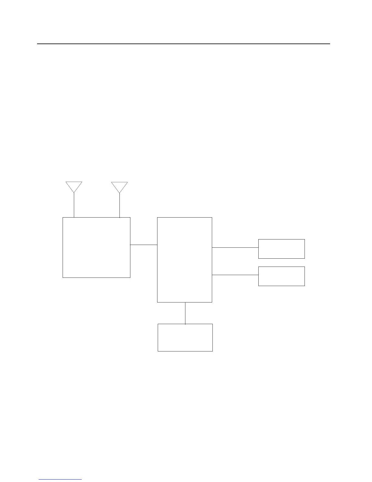
Figure 3-1. APX 2000/ APX 4000/ APX 4000Li Overall Block Diagram
RF+GPS
ntenna
Main Board
Keypad
External Accessory
Connector
Controls Top
Front Display
Bluetooth
Antenna

 Loading...


