3-42 Theory of Operation: Controller
3.2.6 User Interface
3.2.6.1 Top Control
3.2.6.1.1 APX 2000/ APX 4000/ APX 4000Li
The Top Control contains a multifunction knob functioning as ON/OFF switch, Volume and channel
switch, and an emergency button. The Top Control also includes a TX/RX LED that is solid amber
upon receive, red on PTT, and blinks amber on secure RX and a status LED. The Top Control
components are mounted on flex except the emergency button which connects to the Main board
connector J2302.
When the On/Off switch is pressed, the switch is grounded and IGN_X is pulled low. IGN_X is an
input to MAKO (U6501). The logic low input enables an external FET (Q6501) gate voltage,
FET_ENX, which switches UN_SW_B+ to SW_B+ and turns the radio on. The volume and channel
switch is controlled by the multifunction knob. The knob is biased by 1.85V through R2 and R3 on the
Front kit flex. When the knob is rotated, the signals are converted to binary code and are ready by
OMAP through RSW_A, RSW_B and RSW_INT. Pressing the knob once and rotating the knob will
change the volume.
The orange programmable Top Button (S1) is typically used for emergency. It is also biased to
1.875 V (R6507) and is an input (EMERG_BTN_X) to the CPLD. A button press is detected when
EMERG_BTN_X is pulled low.
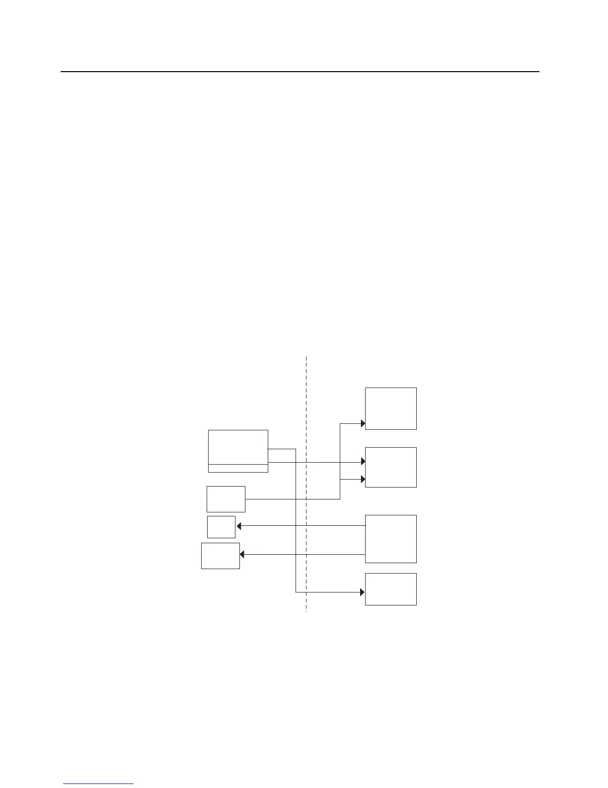
Figure 3-32. Control Top Block Diagram (APX 2000/ APX 4000/ APX 4000Li/ APX 1000 (900 MHz))
CPLD
Frequency/
Volume Switch
ON/OFF SW
Emergency
Switch
MAKO
Status
LED
TX/RX
LED
Intelligent
Lighting
OMAP
Top Control Main Bd

 Loading...


