7-16 Troubleshooting Tables: List of Board and IC Signals
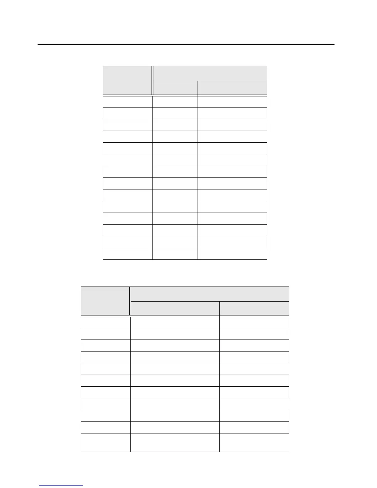
Table 7-7. Front kit connector Interface Pin-Out
Test Place
Front Kit Flex
Signal Name Pin #
GND J1-1
GND J1-2
SIDE_1 J1-3
PTT J1-4
GND J1-5
GND J1-6
SIDE_2 J1-7
MONITOR J1-8
GND J1-9
GND J1-10
GND J1-G1
GND J1-G2
GND J1-G3
GND J1-G4
Test Place
Front Kit Flex
Signal Name Pin #
GND J2-1
SPEAKER_RED_1 J2-2
GPIO_3_RTS_FILLSENSE J2-3
SPEAKER_GREEN_1 J2-4
GPIO_2_DM_RXDC_FILLDATA J2-5
SPEAKER_AMBER_1 J2-6
GPIO_1_DP_TXDC_FILLREQ J2-7
SW_5+ J2-8
GCAI_1WIRE_5V J2-9
SW_5+ J2-10
GPIO_4_CTS_KEYFAIL_FILLCL
K
J2-11

 Loading...


