Troubleshooting Procedures: Power-Up Self-Check Diagnostics and Repair (Not for Field Use) 4-5
4.5 Power-Up Self-Check Diagnostics and Repair (Not for Field Use)
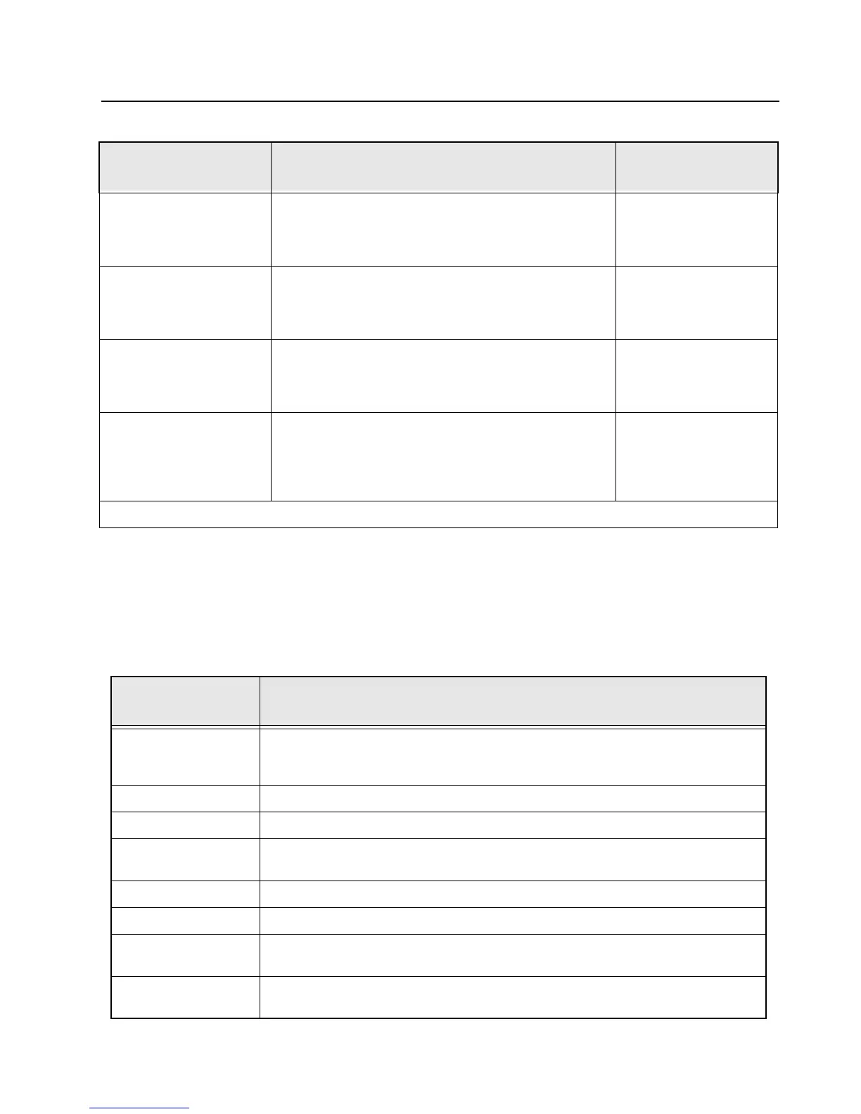
Table 4-5 lists additional action items that can be used for the diagnosis and resolution of the error
codes listed in Table 4-4.
Hardware board absent/
Hardware board absent
then
Man-Down Hw error
Keypad board is not connected properly to the radio Ensure the Keypad board
is fixed in place
15/10 External Accessory Non-Fatal Error
External Accessory is not present on power up or did not
power up correctly, and external accessory feature is
enabled in codeplug.
Verify external accessory
is connected and powers
up. Turn the radio off,
then on.
15/90 External Accessory Fatal Error
External Accessory is not present on power up or did not
power up correctly, and external accessory feature is
enabled in codeplug.
Verify external accessory
is connected and powers
up. Turn the radio off,
then on.
1E/10 Collaborative device is connected to the radio but the
collaborative feature is not enabled in the codeplug.
Contact your Motorola
Sales Representative/
Partner on how to add
Collaborative feature to
your radios.
Note: If the corrective action does not fix the failure, send the radio to the depot.
Table 4-5. Power-Up Self-Check Diagnostic Actions
Error Code/ Error
Message
Diagnostic Actions
01/02 This non-fatal error will likely recover if the radio's power is cycled. In the event that this
does not resolve the issue, the radio should be reflashed. If the error remains, send the
radio to depot.
01/12 The radio should be sent to the depot for reflashing of the security codeplug.
01/20 Cycling radio power should resolve this issue.
01/22 The radio should be sent to the depot for reflash of the tuning codeplug followed by
retuning of the radio.
01/81 The radio should be sent to the depot for reflashing of the host code.
01/82 The radio should be sent to the depot for reflashing of the radio codeplug.
01/88 Reflashing of the radio should first be performed. If this fails to resolve the issue, send
the radio to depot.
01/90 Cycle power to radio. Continued failure indicates a likely IC failure In this event, radio
should be sent to the depot for isolation and repair of the problem IC.
Table 4-4. Power-Up Self-Check Error Codes (Continued)
Error Code/ Error
Message
Description Corrective Action

 Loading...


