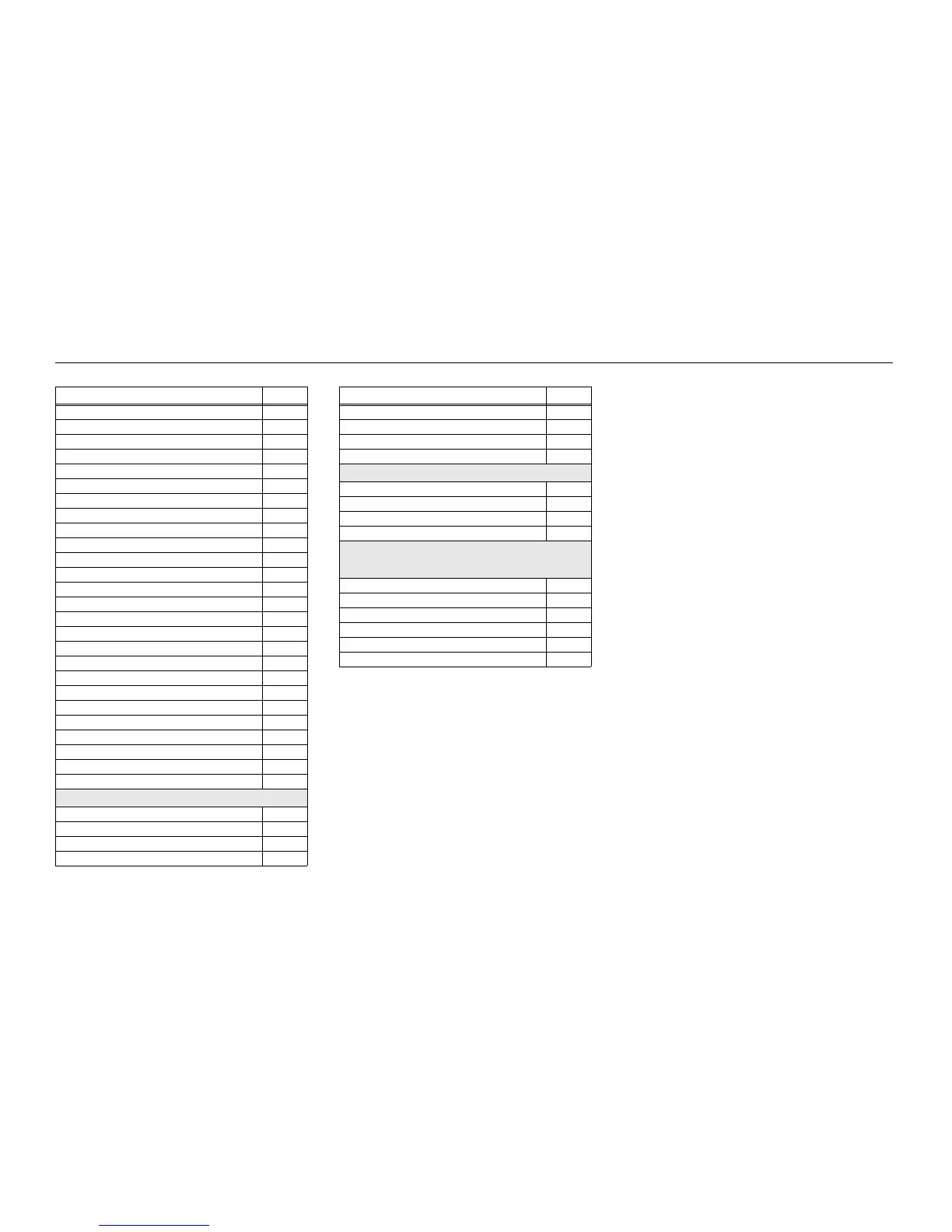
Schematics, Boards Overlays, and Parts Lists: List of Transceiver Schematics and Board Overlays 8-3
Transceiver (RF) Board Overall Schematic 8-339
Controller Mainboard Circuit 8-340
DC Circuit 8-341
Receiver Back End Circuit 8-342
Receiver Front End Circuit 8-343
ANTSWI Circuit 8-344
Automatic Level Control Circuit 8-345
Receiver Back End Circuit 8-346
Frequency Generation Unit Circuit – 1 of 2 8-347
Frequency Generation Unit Circuit – 2 of 2 8-348
Power Amplifier Circuit 8-349
Transmitter HF Circuit 8-350
Receive and Transmit VCO Circuit 8-351
CPLD Circuit 8-352
OMAP User Interface Circuit 8-353
Memory Interface Circuit 8-354
Audio Circuit 8-355
MAKO/DC Distribution Circuit 8-356
Serial Interface Circuit 8-357
RF Interconnects Circuit 8-358
Controller Circuit 8-359
Display/Keypad Lighting Control Circuit 8-360
LCD and Keypad Connector Circuit 8-361
GCAI MACE BT Interconnect Circuit 8-362
Transceiver (RF) Board Layout – Top Side 8-363
Transceiver (RF) Board Layout – Bottom Side 8-364
Keypad Board (APX 2000/ APX 4000/ APX 4000Li) : 84012282001
Keypad Board Overall Circuit Schematic (Basic) 8-383
Keypad Matrix Circuit (Basic) 8-384
Keypad Board Overall Circuit Schematic (Expanded) 8-385
Keypad Matrix Circuit (Expanded) 8-386
Table 8-1. List of Transceiver Schematics and Board Overlays (Continued)
Transceiver Board Schematic/Board Layout Page No.
GPS Bluetooth Circuit 8-387
MACE Circuit 8-388
Keypad Board Layout – Top Side 8-389
Keypad Board Layout – Bottom Side 8-390
Keypad Lite Board: 84012559001
Keypad Lite Board Overall Circuit Schematic 8-405
Keypad Lite Matrix Circuit 8-406
Keypad Lite Board Layout – Top Side 8-407
Keypad Lite Board Layout – Bottom Side 8-408
Keypad Board (APX 2000/ APX 4000 (Two Knobs)) :
PC000356A02 (Model 2)
PC000356A01 (Model 3)
Keypad Board Overall Circuit Schematic (Expanded) 8-411
Keypad Matrix Circuit (Expanded) 8-412
GPS Bluetooth Circuit 8-413
MACE Circuit 8-414
Keypad Board Layout – Top Side 8-415
Keypad Board Layout – Bottom Side 8-416
Table 8-1. List of Transceiver Schematics and Board Overlays (Continued)
Transceiver Board Schematic/Board Layout Page No.

 Loading...


