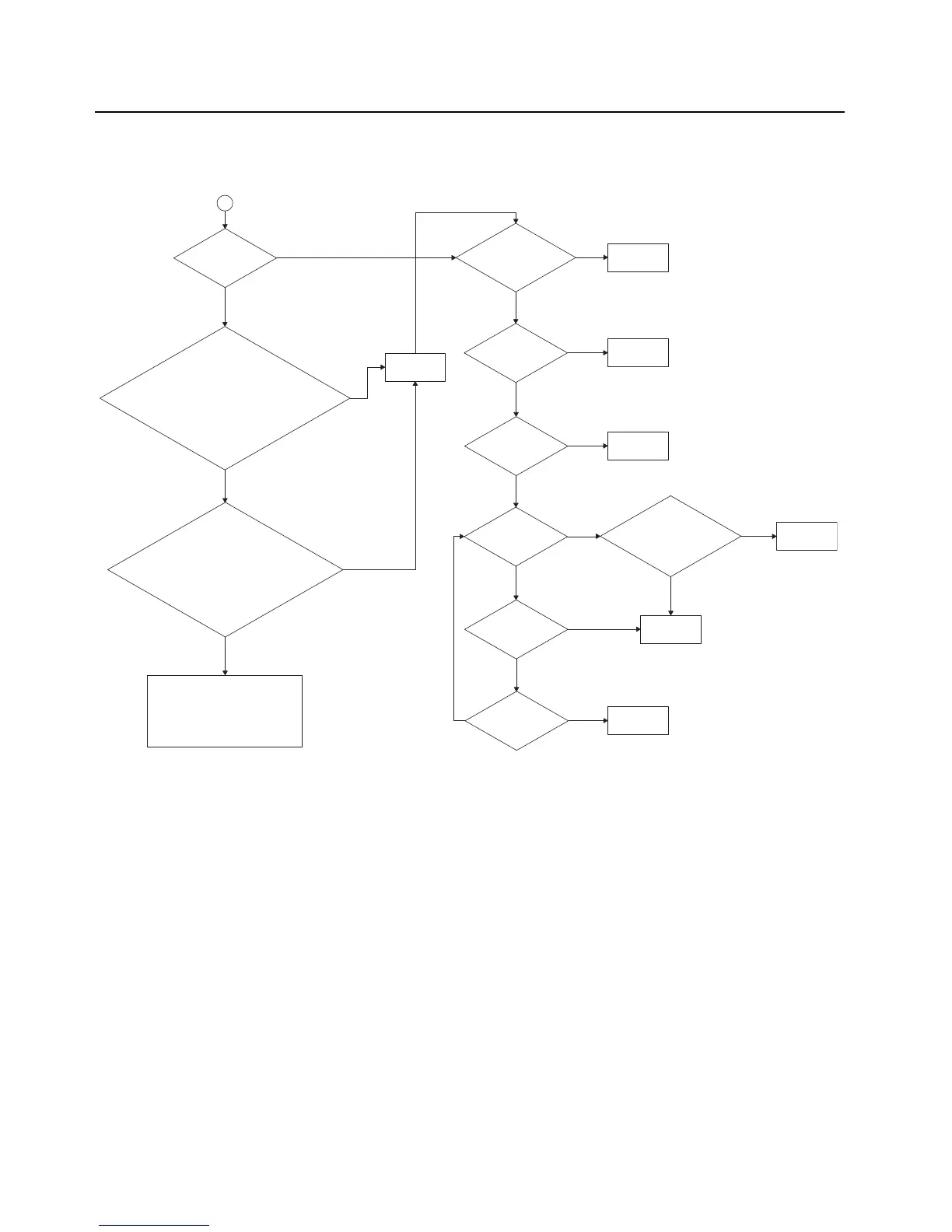
Take continuity
check of traces to
U702.
2
Control voltage
at R705
0.3<Vdc<10.6?
At Tx 764-776MHz, Rx 851-870MHz, is
R3018 high?
or
At Tx 851-870MHz, Rx 764-776MHz, is
R3052 high?
or
At Tx 794-824MHz, is R3019 high?
At Tx 764-776MHz, Rx 851-870MHz, is
Vdc at Q3038 4.55V?
or
At Tx 851-870MHz, Rx 764-776MHz, is
Vdc at Q3062 4.55V?
or
At Tx 794-824MHz,
Vdc at Q3039 4.55V?
At Tx 764-776MHz, Rx 851-870MHz, check and visual
inspect VR3010, C3014, C3015, C3022, C3023, Y3020.
At Tx 851-870MHz, Rx 764-776MHz, check and visual
inspect VR3048, C3050, C3051, C3054, C3055, Y3053.
At Tx 794-824MHz, check and visual inspect VR3011,
C3016, C3017, C3024, C3025, Y3021.
Is Vdc at C742 5V,
Vdc at C726, C734,
C737 2.775V?
Is Vdc at Y701
pin 4 2.775V?
16.8MHz at pin
3 of Y701 and
C736?
16.8MHz at
L753?
10.8Vdc at pin2
of D723?
2.775Vdc at pin
4 of D722?
Check and visual
inspect U746 circuitry.
Fault found?
Check 2.775V and
5V supply.
Check 2.775V
supply.
Replace Y701
and/or C736.
Replace the
suspected
components.
Replace U702.
Check D722, D723,
C716, C717, C718,
C719.
Yes
No
No
No
Yes
Yes
Yes
Yes
No
No
No
No
No
No
Yes
Yes
No
Yes
Yes
Yes

 Loading...


