Troubleshooting Charts: PA Failure 5-61
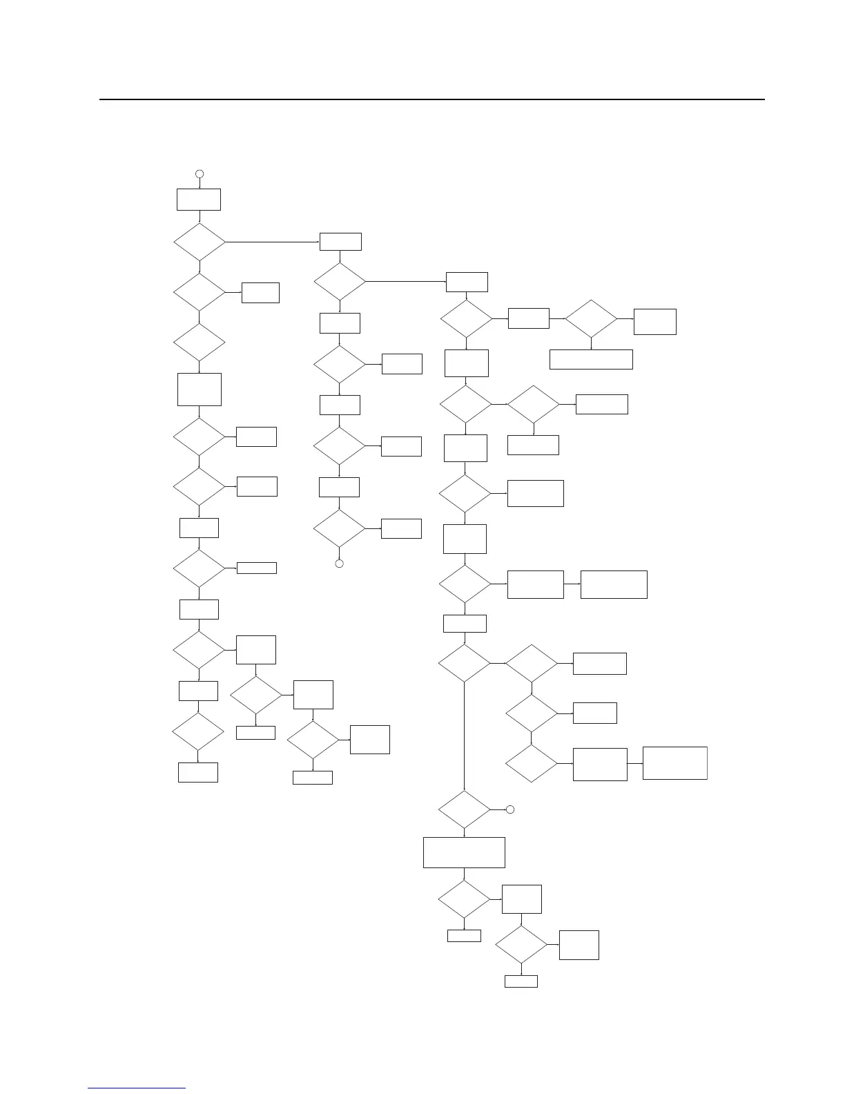
PA Failure – Page 2 (700/800 MHz PA)
Measure TX current
at 700_800MHz test
frequencies
Yes
No
2
Measure DC voltage
at pin 4 of U1001
Yes
Is current less
than 350mA?
Measure voltage at
pin 5 of U1001
Replace Q1001
Yes
No
Is current
approximately
500mA?
Yes
No
Is voltage
approximately 6V
at DAC=4095?
Is current greater
than or close to
2A?
Use a spectrum
analyzer and high-
impedance RF
probe. Measure
RF_IN_1 at C1001.
Yes
Yes
Is the frequency
correct?
No
See FGU
troubleshooting
charts
Yes
Is the power
level about 3 dBm?
No
See FGU
troubleshooting
charts
Measure power at
C1022
Yes
Is the power
approximately
37 dBm?
No
Replace Q1001
Measure power at
C2304
Is the power
approximately
37 dBm?
No
Check D2303
positive node
voltage
Measure power at
C1411
Is the power
approximately
37 dBm?
Check power out at
C1122 and for any
process issue
Yes
Is the voltage
near 7.0V?
No
Replace D2303
Yes
Check pin 3 and
pin 2 of Q2301
Is pin 3 of
Q2301=Raw B+
and pin 2=3.0V
No
Replace Q2301
Yes
Check continuity of
R2305 and L2302
Measure voltage at
pin 3 of Q1101
Yes
No
Is voltage
approximately
7V?
Yes
No
Is voltage
approximately
0V?
Replace U1001
Replace Q1103
Measure voltage at
pin 1 of Q1101
Yes
No
Is voltage greater
than 1.5V?
Replace Q1101
5
Measure DC voltage
at pin 5 of U1001
Was voltage
near 7.5V?
Measure voltage at
pin 1 of Q1101
No
Yes
With the radio in RX
mode, measure the
DC voltage on both
pins of L1003
Was voltage
near 7.5V on
both sides?
No
Yes
Is there 7.5V
on C1008?
No
Check E1101 for
solderability issues and
replace as necessary
Yes
Check L1003 for
solderability issues and
replace as necessary
Was voltage
near 3V?
No
Measure the logic
inputs of TXH_1
from R1111 and
TX_INH from U1138
Yes
Trace voltages and check for solderability
issues on R1102, Q1101, and Q1103.
Replace parts as necessary.
With the radio in RX
mode, measure the
DC voltage on the
drain of Q1001
Was voltage
near 7.5V?
No
Check L1007 under shield
SH1 for solderability
issues and replace as
necessary
With the radio in RX
mode, measure the
resistance on the
node shared by
R1006 and R1005
Yes
Is the resistance
near 9.4 kOhms?
No
Check resistors R1001,
R1002, R1003, R1004,
and R1005 for resistance
and solderability issues
and replace as necessary
In TX mode,
measure the voltage
on pin 4 of U1001
Yes
If resistance is very low, in the
100’s of ohms, and there are no
issues with the resistors then
there is a gate short on the PA.
Clear short or replace Q1001.
Is the voltage
near 6V?
Yes
Is TX current just
above standby
current?
Yes
Is the TX current
between 300 and
900mA?
Yes
Is the TX current
above 900mA?
Yes
Is the voltage
below 4V?
Yes
The PA and Driver are
likely damaged. Replace
Q1001 and U1002.
The PA is likely
damaged. Replace
Q1001.
Lift shield SH1 and check
for solderability or part
issues on all 900 series
parts. Replace parts as
necessary.
If no issues found, lift shield
SH8 and check for solderability
or part issues on all 1200
series parts. Replace parts as
necessary.
5
If the voltage is between 4 and 5.5V then
the control loop should be working and
power should be available. Check D2303
positive node voltage.
No
Is the voltage
near 7.0V?
Yes
No
Check pin 3 and
pin 2 of Q2301
Is pin 3 of
Q2601=Raw B+
and pin 2=3.0V
Yes
No
Check continuity of
R2305 and L2302
Replace Q2301
Replace D2303
Yes

 Loading...


