EasyManuals Logo

Motorola APX 2000 Detailed Service Manual

Motorola APX 2000
1096 pages
To Next Page IconTo Next Page
To Previous Page IconTo Previous Page
Page #727 background imageLoading...
Page #727 background image
Theory of Operation: Controller 3-23
3.2.1.3 Controller Electrical Architecture
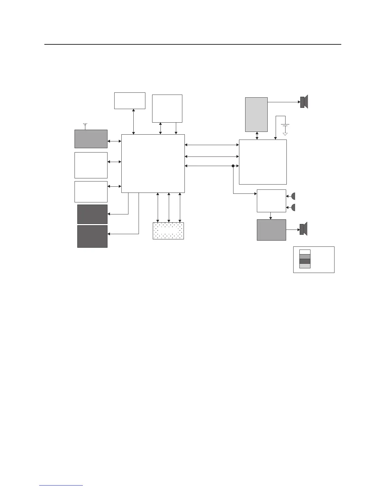
An overview of the Controller electrical architecture is shown in Figure 3-14 below. The major
components and electrical interfaces are shown.
Figure 3-14. Controller Electrical Overview
The functional blocks of the controller are:
DC Distribution
Clock Sources
Processor / Memory
•CPLD
Audio – Internal and External
MAKO
User Interfaces
GPS/ BT Chipset
(TINL5500)
FLASH
64MB
SDRAM
32MB
Keypad /
Switches
Front
Display
SoSSI
Keypad
EMIFF
EMIFS
UART 2
12C
Lighting
Controller
CPLD
EMIFS
32 kHz Clk
Side
Conn -
GCAI
Radio
Battery
Accessory
Audio
MAKO IC
SPI
Codec
Dual
Microphones
Main
Speaker
Main Board
Keypad
UI
GCAI
Class D
Audio PA
RF Section
GPIO SPI SSI
SPI
USB / UART
Audio SSI 1
OMAP 1710
Processor
+
-

Table of Contents

Other manuals for Motorola APX 2000

Questions and Answers:

Question and Answer IconNeed help?

Do you have a question about the Motorola APX 2000 and is the answer not in the manual?

Motorola APX 2000 Specifications

General IconGeneral
IP RatingIP67
Operating Temperature-30°C to +60°C
GPSOptional
BluetoothNo
Frequency Range700/800 MHz
Power Output1-5 W (VHF), 1-3 W (700/800 MHz)
ChannelsUp to 1, 000
Battery LifeUp to 10 hours (digital)
Digital ProtocolAPCO P25
FrequencyVHF: 136-174 MHz, UHF: 380-470 MHz, 700/800 MHz: 764-870 MHz
Power1-3W (700/800 MHz), 1-5W (VHF)

Related product manuals