3-30 Theory of Operation: Controller
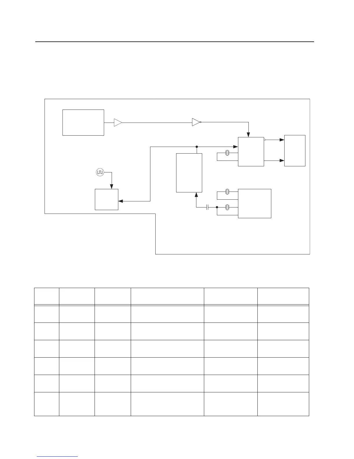
3.2.3 Clock Sources
The main board and keypad board contains multiple crystal clock sources. These sources are active
upon power-up. The controller receives a 16.8 MHz sine wave from the RF section, which is shaped
into square wave and fed to the OMAP timer input. Screen shots and test points for these clock
signals are shown in Chapter 6.
Figure 3-19. Controller Clock Architecture
Table 3-5. Controller Clock Distribution
Clock
Source
Frequency Type Description Clock Recipient Suggested Probe
Points
Y6501 24.576 MHz Crystal
Oscillator
MAKO 24 MHz & tapped into
CPLD
U6501, U6101 R6574
Y6502 32.768 kHz Crystal
Oscillator
MAKO RTC U6501 C6541
Y6601 12 MHz Crystal
Oscillator
OMAP CPU Clock U6302 C6601
U6302 96 MHz OMAP GPIO DDR Clocks
(Complementary signals)
U6301 TP6307 & TP6308
U6101 32.768 kHz CPLD GPIO OMAP Boot-Up clock & GPS/
Bluetooth digital clock
U6302 & U2401
(Keypad Board)
R6114 (GPS/BT) &
R6115 (OMAP)
Y701
(RF
board)
16.8 MHz Crystal
Oscillator
RF Frequency Synthesizer
IC (Trident) TCXO
U6302 R6218
GPS
26 MHz
OMAP
MAKO
CPLD
DDR
SQUARING
TRIDENT
24.576 MHz
32.768 kHz
12 MHz
32.768 kHz
16.8 MHz
96 MHz
Main Board

 Loading...


