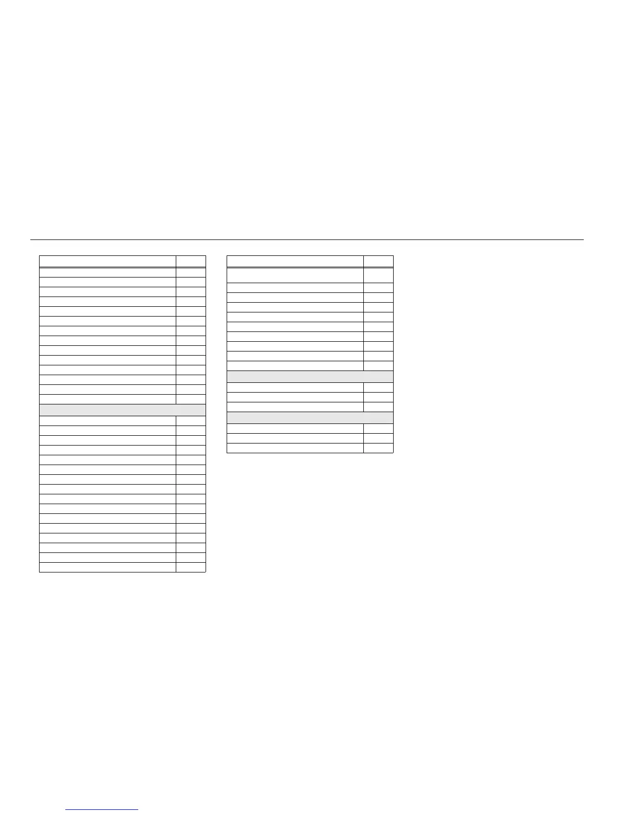
8-2 Schematics, Boards Overlays, and Parts Lists: List of Transceiver Schematics and Board Overlays
CPLD Circuit 8-151
OMAP User Interface Circuit 8-152
Memory Interface Circuit 8-153
Audio Circuit 8-154
MAKO/DC Distribution Circuit 8-155
Serial Interface Circuit 8-156
RF Interconnects Circuit 8-157
Controller Circuit 8-158
Display/Keypad Lighting Control Circuit 8-159
LCD and Keypad Connector Circuit 8-160
GCAI MACE BT Interconnect Circuit 8-161
GPS Circuit 8-162
Transceiver (RF) Board Layout – Top Side 8-163
Transceiver (RF) Board Layout – Bottom Side 8-164
700/800 MHz : 84012619001
Transceiver (RF) Board Overall Schematic 8-179
Controller Mainboard Circuit 8-180
DC Circuit 8-181
Receiver Back End Circuit 8-182
Receiver Front End Circuit 8-183
ANTSWI Circuit 8-184
Automatic Level Control Circuit 8-185
Receiver Back End Circuit 8-186
Frequency Generation Unit Circuit – 1 of 2 8-187
Frequency Generation Unit Circuit – 2 of 2 8-188
Power AmplifierCircuit 8-189
Transmitter HF Circuit 8-190
VCO Circuit 8-191
CPLD Circuit 8-192
OMAP User Interface Circuit 8-193
Memory Interface Circuit 8-194
Table 8-1. List of Transceiver Schematics and Board Overlays (Continued)
Transceiver Board Schematic/Board Layout Page No.
Audio Circuit]MAKO/DC
Distribution Circuit
8-195
Audio Circuit]MAKO/DC Distribution Circuit 8-195
Serial Interface Circuit 8-196
RF Interconnects Circuit 8-197
Controller Circuit 8-198
Display/Keypad Lighting Control Circuit 8-199
LCD and Keypad Connector Circuit 8-200
GCAI MACE BT Interconnect Circuit 8-201
Transceiver (RF) Board Layout – Top Side 8-202
Transceiver (RF) Board Layout – Bottom Side 8-203
Keypad Board: 84012686001
Keypad Board Overall Circuit Schematic (Basic) 8-225
Keypad Board Layout – Top Side 8-226
Keypad Board Layout – Bottom Side 8-227
Keypad Lite Board: PC000261A01
Keypad Lite Board Overall Circuit Schematic
8-229
Keypad Lite Board Layout – Top Side 8-230
Keypad Lite Board Layout – Bottom Side 8-231
Table 8-1. List of Transceiver Schematics and Board Overlays (Continued)
Transceiver Board Schematic/Board Layout Page No.

 Loading...


