47
Transmit Deviation
Limit Alignment
From the MAIN MENU, press F2 twice and then F5 to access the
TRANSMIT DEVIATION LIMIT screen.
VCO Attenuator Alignment is required after replacing (or servicing) the
Controlled Board or the RF Board. This alignment procedure limits the
modulation of a baseband signal. It is used for primary modulation
limiting. This procedure needs to be performed at multiple frequencies
to allow for proper alignment across the entire RF band. The RF band
is divided into frequency zones with a calibration point (value) in each
zone.
Refer to your Radio Service Manual for the Transmit Deviation Limit
Alignment procedure.
Programming Procedure 1. Press F6 to key up the radio. (The radio’s RF output must be
terminated into a 50 ohm load.)
2. Apply the appropriate signal according to instructions in your
Radio Service Manual.
3. While transmitting, modify the Balance Attenuator setting using
the UP/DOWN arrow keys. To increase the adjustment speed, use
the Shift-UP/DOWN arrow keys.
4. A relative Tx power value will be displayed, but you must
determine the actual transmitter power output from the service
monitor.
5. Press F6 to de-key the radio and Tab to move between frequency
points.
6. Press F8 to save the new value.
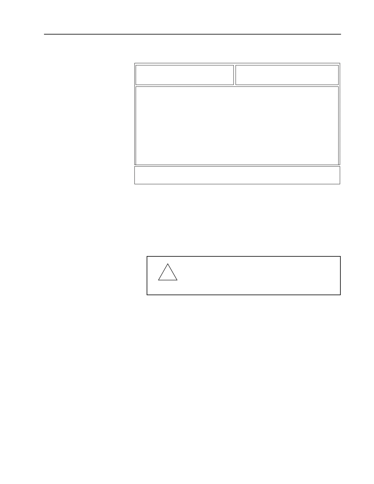
BBE
MOTOROLA Radio Service Software Use UP/DOWN Arrows To Adjust Softpot.
MCS Model:
...TRANSMIT DEVIATION LIMIT
TRANSMIT DEVIATION LIMIT
------------------------
Current
Frequency Value New Softpot Value
--------- ------- -----------------
136.0125 176 176
144.0125 177 177
154.0125 177 177
160.0125 177 177
167.5125 177 177
173.9875 179 179
177.9875 178 Transmitter..Off 178
0 255
MIN |----+----+----+----+----+----+----+----+X---+----+----+----| MAX
F1 F2 F3 F4 F5 F6 F7 F8 F9 F10
HELP TOGGLE PROGRAM EXIT
PTT VALUE
!
Caution
This procedure should be attempted only by qualified
service personnel. Failure to perform alignment
procedures properly may result in seriously degraded
radio or system performance.

 Loading...


