Sample Applications of VLANs Using Moxa Switches
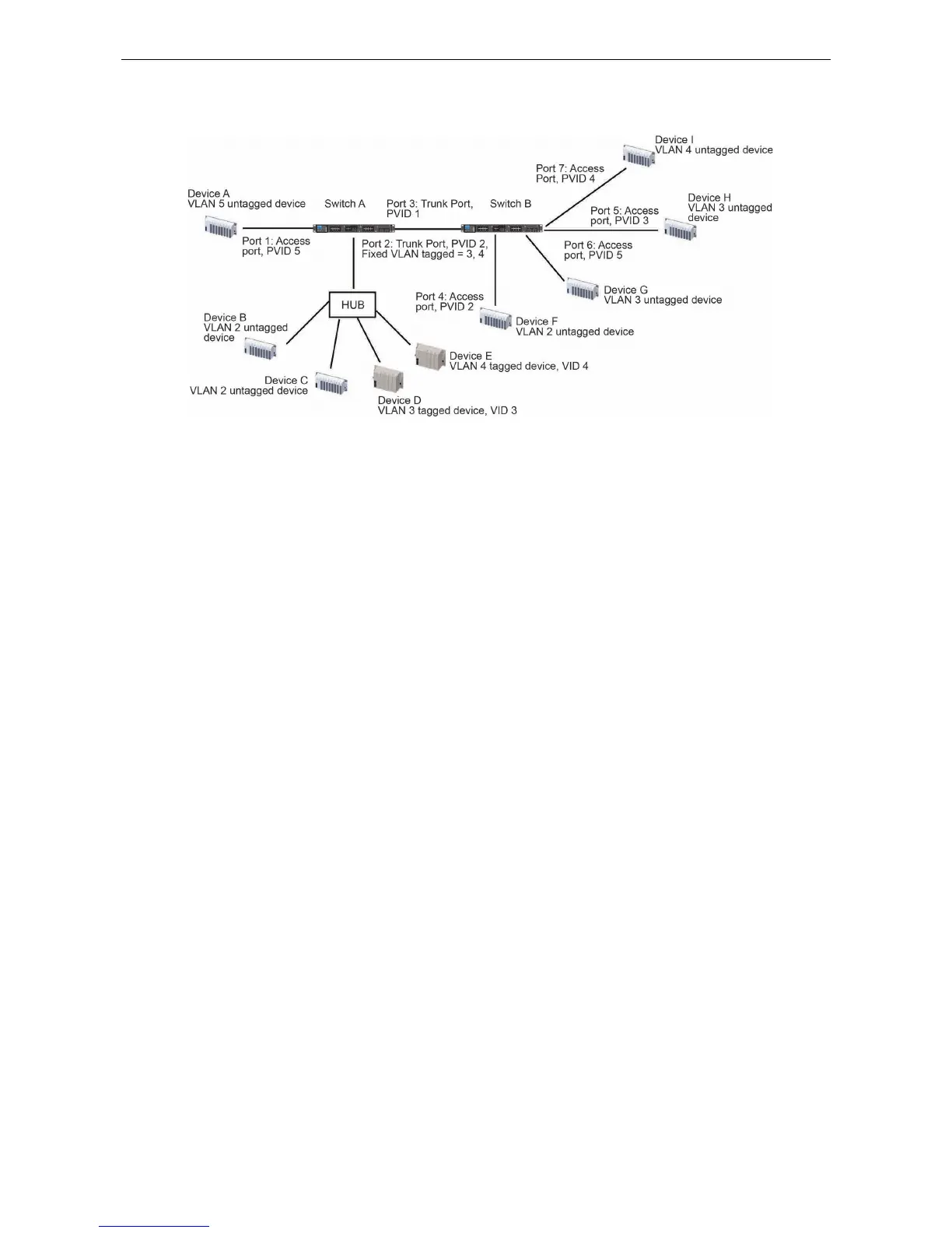
In this application,
• Port 1 connects a single untagged device and assigns it to VLAN 5; it should be configured as Access Port
with PVID 5.
• Port 2 connects a LAN with two untagged devices belonging to VLAN 2. One tagged device with VID 3 and
one tagged device with VID 4. It should be configured as Trunk Port with PVID 2 for untagged device and
Fixed VLAN (Tagged) with 3 and 4 for tagged device. Since each port can only have one unique PVID, all
untagged devices on the same port must belong to the same VLAN.
• Port 3 connects with another switch. It should be configured as Trunk Port GVRP protocol will be used
through the Trunk Port.
• Port 4 connects a single untagged device and assigns it to VLAN 2; it should be configured as Access Port
with PVID 2.
• Port 5 connects a single untagged device and assigns it to VLAN 3; it should be configured as Access Port
with PVID 3.
• Port 6 connect a single untagged device and assigns it to VLAN 5; it should be configured as Access Port
with PVID 5.
• Port 7 connects a single untagged device and assigns it to VLAN 4; it should be configured as Access Port
with PVID 4.
After the application is properly configured:
• Packets from Device A will travel through Trunk Port 3 with tagged VID 5. Switch B will recognize its VLAN,
pass it to port 6, and then remove tags received successfully by Device G, and vice versa.
• Packets from Devices B and C will travel through Trunk Port 3 with tagged VID 2. Switch B recognizes its
VLAN, passes it to port 4, and then removes tags received successfully by Device F, and vice versa.
• Packets from Device D will travel through Trunk Port 3 with tagged VID 3. Switch B will recognize its VLAN,
pass to port 5, and then remove tags received successfully by Device H. Packets from Device H will travel
through Trunk Port 3 with PVID 3. Switch A will recognize its VLAN and pass it to port 2, but will not
remove tags received successfully by Device D.
• Packets from Device E will travel through Trunk Port 3 with tagged VID 4. Switch B will recognize its VLAN,
pass it to port 7, and then remove tags received successfully by Device I. Packets from Device I will travel
through Trunk Port 3 with tagged VID 4. Switch A will recognize its VLAN and pass it to port 2, but will not
remove tags received successfully by Device E.