Multicomp-Pro
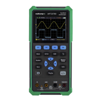
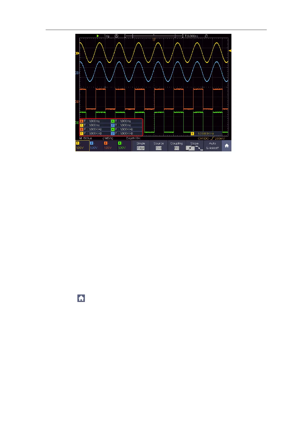
Figure 7-1 Measure period and frequency value for a given signal
Example 2: Gain of a Amplifier in a Metering Circuit
The purpose of this example is to work out the Gain of an Amplifier in a
Metering Circuit. First we use Oscilloscope to measure the amplitude of input
signal and output signal from the circuit, then to work out the Gain by using
given formulas.
Set the probe menu attenuation coefficient as 10X and that of the switch in the
probe as 10X (see "How to Set the Probe Attenuation Coefficient" on P11).
Connect the oscilloscope CH1 channel with the circuit signal input end and the
CH2 channel to the output end.
Operation Steps:
(1) Push the Autoset button and the oscilloscope will automatically adjust the
waveforms of the two channels into the proper display state.
(2) Click to call up the menu panel. Click the Measure softkey on panel to
display the Measure menu.
(3) Select Add in the bottom menu.
(4) In the left Type menu, select PK-PK.
(5) In the right menu, select CH1 in the Source menu item.
(6) In the right menu, select Add. The peak-to-peak type of CH1 is added.
(7) In the left Type menu, select PK-PK.
(8) In the right menu, select CH2 in the Source menu item.
(9) In the right menu, select Add. The peak-to-peak type of CH2 is added.
(10) Read the peak-to-peak voltages of Channel 1 and Channel 2 from the