Multicomp-Pro
If the channel is under the DC coupling mode, you can rapidly measure the DC
component of the signal through the observation of the difference between the
wave form and the signal ground.
If the channel is under the AC mode, the DC component would be filtered out.
This mode helps you display the AC component of the signal with a higher
sensitivity.
Vertical offset back to 0 shortcut key
Turn the upper knob to change the vertical display position of the selected
channel, and push the upper knob to set the vertical display position back to 0
as a shortcut key, this is especially helpful when the trace position is far out of
the screen and want it to get back to the screen center immediately.
3. Change the Vertical Setting and Observe the Consequent State Information
Change.
With the information displayed in the status bar at the bottom of the waveform
window, you can determine any changes in the channel vertical scale factor.
Turn the lower knob and change the "Vertical Scale Factor (Voltage Division)"
of the selected channel, it can be found that the scale factor of the selected
channel in the status bar has been changed accordingly.
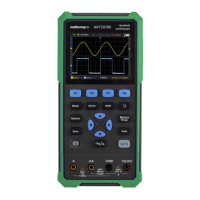
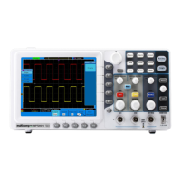
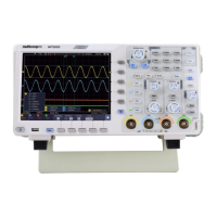
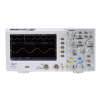
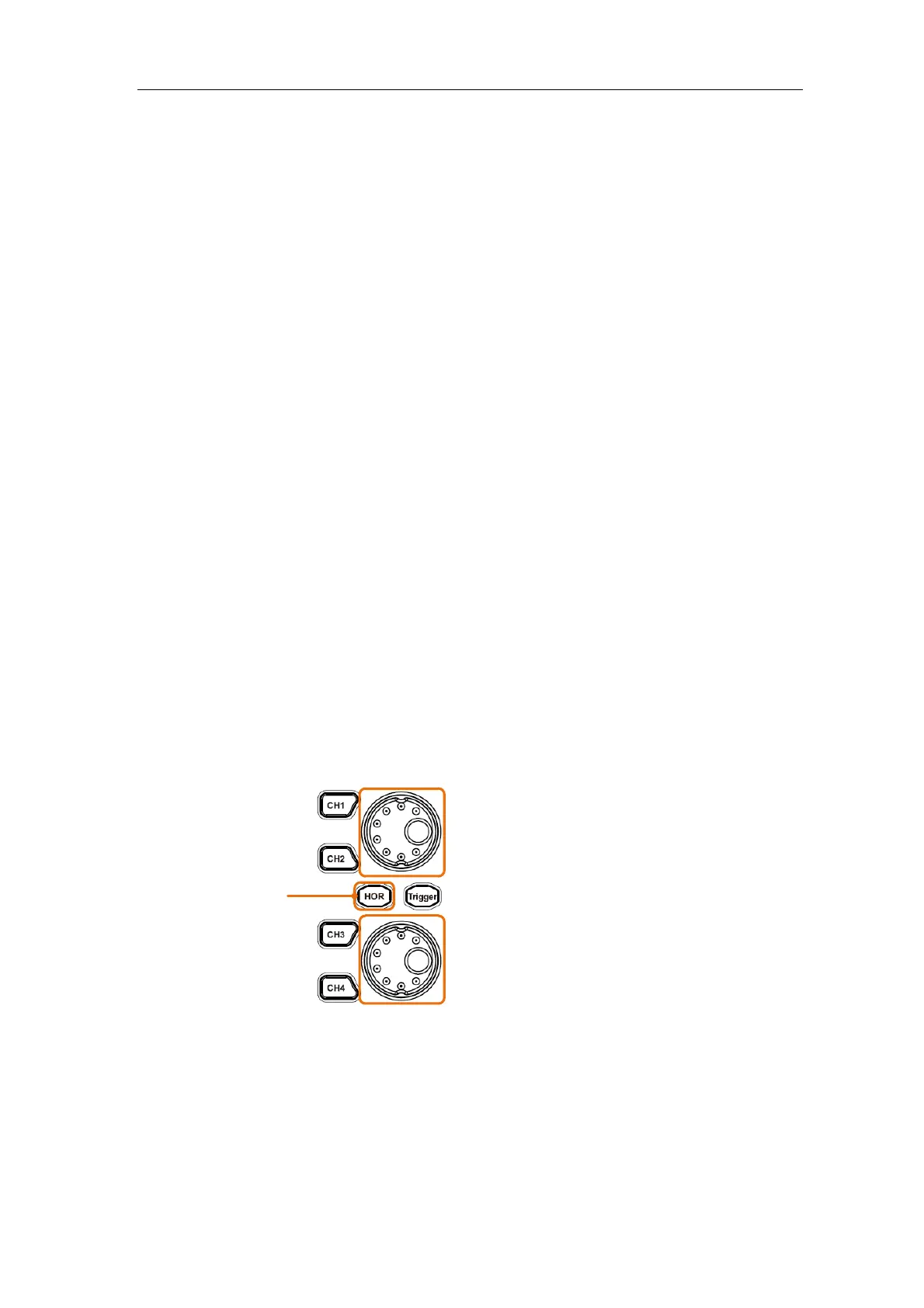
Introduction to the Horizontal System
Shown as Figure 3-11, there are a button and two knobs in the Horizontal
Controls. The following practices will gradually direct you to be familiar with the
setting of horizontal time base.
Upper knob: adjust horizontal position
When the HOR
button is lit
Lower knob: adjust horizontal scale
Figure 3-11 Horizontal Control
1. When the HOR button is lit, push the HOR button to switch between the
normal mode and the wave zoom mode.
2. When the HOR button is lit, turn the lower knob to change the horizontal
time base setting and observe the consequent status information change.
Turn the lower knob to change the horizontal time base, and it can be