Multicomp-Pro
4. USB Host port: It is used to transfer data when external USB equipment
connects to the oscilloscope regarded as "host device". For example: Saving
the waveform to USB flash disk needs to use this port.
5. LAN port: the network port which can be used to connect with PC.
6. Connector for the DC power source via an AC-DC adapter
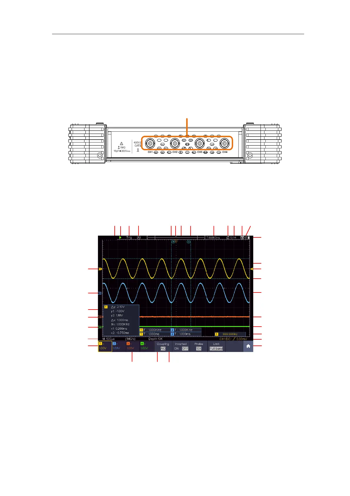
Top Panel
Input connectors of four channels
Figure 3-3 Top Panel
User Interface Introduction
1
3
9
21
15
29
26
6
8
10
12
16
13
17
22
24
30
32
7
11
27
2
4
5
25
14
5
20
31
18
19
23
28
Figure 3-4 Illustrative Drawing of Display Interfaces
1. Waveform Display Area.
2. Run/Stop (touchable) (see "Use Executive Buttons" on P97)
3. The state of trigger, including:
Auto: Automatic mode and acquire waveform without triggering.
Trig: Trigger detected and acquire waveform.
Ready: Pre-triggered data captured and ready for a trigger. Click the