User Manual
Synchronic trigger in video field
Synchronic trigger in video odd filed
Synchronic trigger in video even field
Synchronic trigger in designed video line, turn the M
rotary control to set the line number
Acquire waveform even no trigger occurred
100 ns – 10 s, adjust the M rotary control to set time
interval before another trigger occur
Set Holdoff time as 100 ns
3. Slope Trigger
Slope trigger sets the oscilloscope as the positive/negative slope trigger within the
specified time.
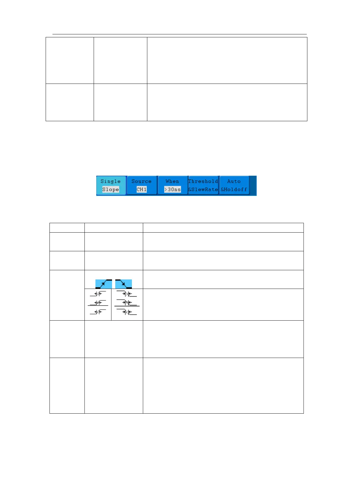
The Slope Trigger Menu is shown as Figure 5-20.
Figure 5-20 Slope trigger menu
Slope trigger menu list:
Set vertical channel trigger type as slope trigger.
Select CH1 as the trigger source.
Select CH2 as the trigger source.
Set slope condition; turn the M rotary control to set
slope time.
High level
Low level
Slew rate
Adjust M rotary control to set the High level upper
limit.
Adjust M rotary control to set Low level lower limit.
Slew rate = (High level - Low level)/ Settings
Auto
Normal
Single
Holdoff
Reset
Acquire waveform even no trigger occurred
Acquire waveform when trigger occurred
When trigger occurs, acquire one waveform then stop
100 ns - 10 s, turn the M rotary control to set time
interval before another trigger occur.
Set Holdoff time as 100 ns
4. Pulse Width Trigger
Pulse trigger occurs according to the width of pulse. The abnormal signals can be detected
through setting up the pulse width condition.
The Pulse Width Trigger Menu is shown as Figure 5-21.