(Revised 2011-07-21) Page 12 of 158
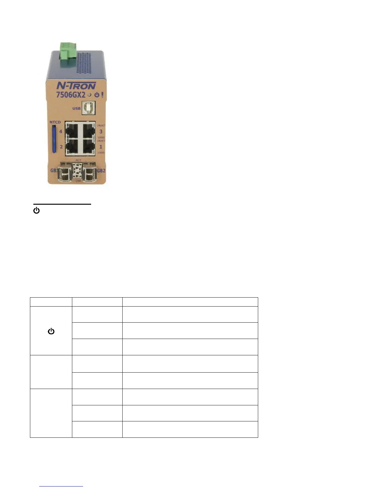
FRONT PANEL
From Top to Left:
LED lights when Power is supplied to the unit
USB Command Line Interface (CLI)
RJ45 Ports Auto Sensing 10/100/1000 Base-T Connections
NTCD N-Tron Configuration Device
Gigabit Ports 1000 Base SFP Fiber Transceivers (Optional)
NOTE: The RJ45 data ports have two LEDs located on each connector. The bottom LED indicates the
SPEED, and the top LED indicates LINK/ACTIVITY.
LEDs: The table below describes the operating modes:
Power is ON and a fault condition exists
Link established, no Activity on cable.
Link established, Activity on cable.
No Link activity between ports
 Loading...