IOM-EZVAVINST
Date: 10-2016 Supersedes: 7-2016
Nailor reserves the right to change any information concerning product or specification without notice or obligation.
Page 29 of 48
Installation and Operation Manual
●
EZvav Digital Controls
Secon7: ApplicaonDrawings
This secon covers the drawings, materials, and instrucons for specic VAV applicaons.
Each EZvav model is designed for a specic set of applicaons. The following topics are for control technicians and engineers that
will plan for and install controllers for EZvav applicaons.
Submial sheets for all of these applicaons are available from the Resources page at www.nailor.com.
Cooling or heang without reheat....................................................................................................29
Staged reheat ....................................................................................................................................30
Modulang reheat ............................................................................................................................31
Floang reheat ..................................................................................................................................32
Dual duct applicaon ........................................................................................................................33
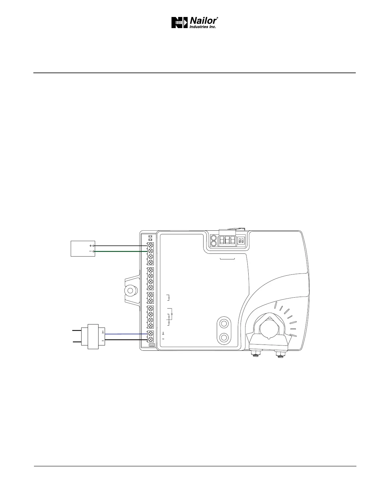
CoolingorHeangwithoutReheat
The BAC-8001-36 is congured for single duct cooling VAV control without reheat. Connect the controller as shown in the Figure
Cooling or heang applicaon drawing as below. A BAC-8005-36 may also be used for this applicaon.
For cooling and heang, a duct temperature sensor is required for Discharge Air Temperature liming and automac changeover.
See the topic Advanced opons on page 21 for instrucons to enable Discharge Air Temperature liming.
Submial sheets for several variaons of this applicaon are available from the Resources page at www.nailor.com.
Figure7-1 Coolingorheangapplicaondrawing
24 VAC
Duct
Temp
Sensor
ON CTS
1 2
COMM
READY
AI1
AI5
GND
AO4
AO3
SC
BO8
BO5
BO6
SC
BO7
24VAC
AI6
GND
AI7
T-STAT/
SENSOR
-A
+B
S
EOL
BACnet MS/TP
 Loading...