IOM-EZVAVINST
Date: 10-2016 Supersedes: 7-2016
Nailor reserves the right to change any information concerning product or specification without notice or obligation.
Page 11 of 48
Installation and Operation Manual
●
EZvav Digital Controls
Secon3:InstallingtheRoomSensors
An airow sensor is incorporated as one of the inputs to the controller. Remove the plugs and connect the tubing from the pitot
assembly to the airow sensor inputs next to the drive hub.
EZvavSensors:
This applies to EZvav digital display wall sensors connected to EZvav controllers.
Choosingasensorlocaon
Install the sensor on an inside wall where it can sense the average room temperature. Avoid locaons with direct sunlight, heat
sources, windows, air vents, and air circulaon obstrucons such as curtains or furniture.
For models with moon sensing, see the topic on the page 12, Planning for moon sensing.
Rough-inpreparaon
Complete rough-in wiring at each sensor locaon prior to sensor installaon. This includes the following items:
• If required, install an appropriate backplate.
• Route an Ethernet connecng cable from the sensor to the controller locaon.
• Maximum cable length is 75 feet (22.9 meters). Plenum-rated preassembled cables are recommended.
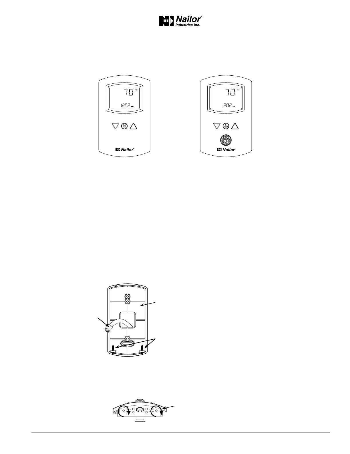
Mount the sensors
To install the sensor on a mounng base, do the following:
1. Turn the Allen screws in the base of the sensor clockwise unl they clear the case. Swing the sensor away from the
mounng base to remove it.
STE-8001W36
DigitalDisplay
STE-8201W36
DigitalDisplaywithOccupancySensor
Mounng
Base
EthernetConnecng
Cable
Maximum75feet
(22.9meters)
Allen
Screws
Turnscrewsclockwiseto
removesensorcasefrombase.