IOM-EZVAVINST
Date: 10-2016 Supersedes: 7-2016
Nailor reserves the right to change any information concerning product or specification without notice or obligation.
Page 9 of 48
Installation and Operation Manual
●
EZvav Digital Controls
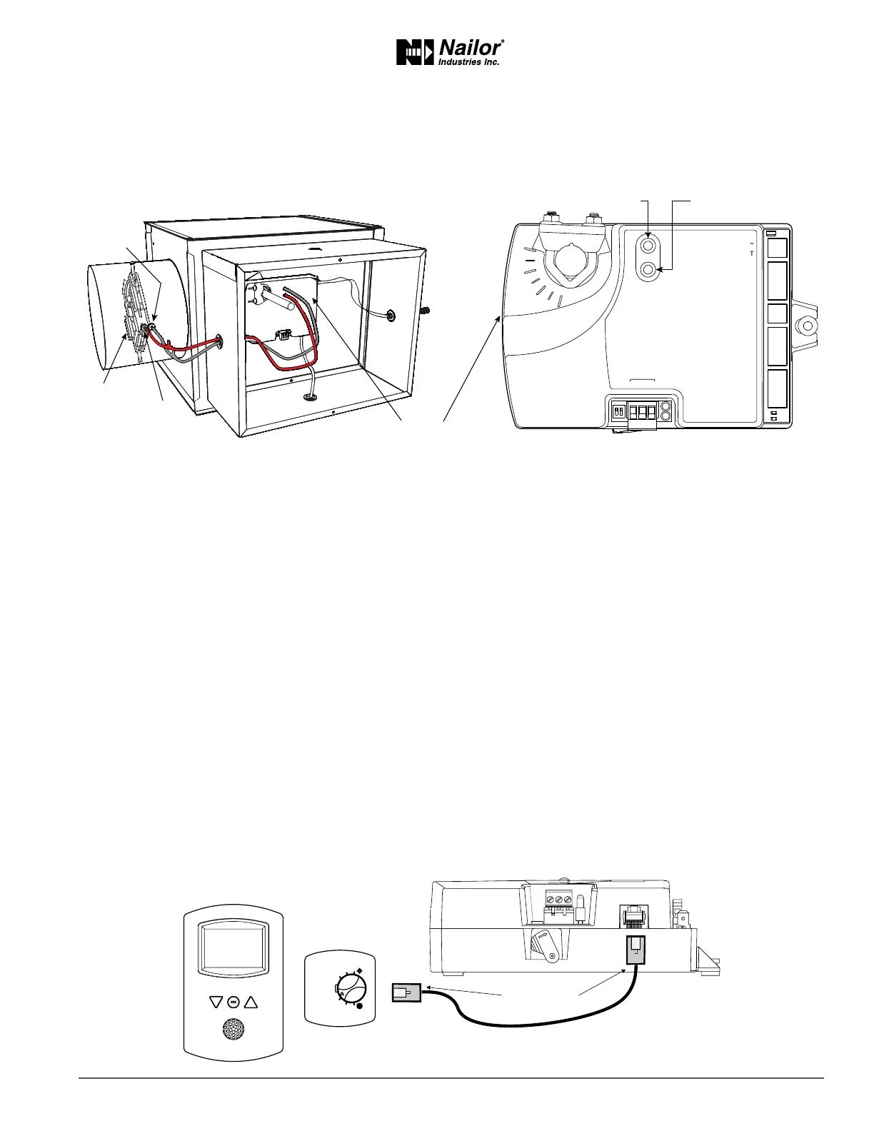
ConnecnganAirowSensor
An airow sensor is incorporated as one of the inputs to the controller. Remove the plugs and connect the tubing from the pitot
assembly to the airow sensor inputs next to the drive hub.
Figure2-3 Airowsensorinputs
Diamond ow sensors are supplied by Nailor as part of the VAV terminal unit. If a sensor is needed, choose a sensor listed in the
topic Accessories and Replacement Parts on page 48. For more informaon on Nailor’s ‘Diamond Flow’ Sensor, see page 48 or
refer to Nailor website.
ConnecngInputsandOutputs
Nailor EZvav series controllers have precongured inputs and outputs to support only the supplied programs and applicaons.
• For input and output connecon informaon, see the topic Applicaon drawings on page 29.
• To connect room temperature sensors, see the topic Connecng room temperature sensors on page 9.
• To connect a DAT sensor, see the topic Connecng a DAT sensor on page 10.
• For the BACnet object descripons of the inputs and outputs, see the topic BACnet objects on page 44.
ConnecngRoomTemperatureSensors
Connect any of the following sensors to the RJ-45 thermostat and sensor jack. The controller automacally detects the type of
sensor. No programming or conguraon is required.
• STE-6014W36
• STE-8001W36
• STE-8201W36
Connect the controller to sensors with standard Ethernet cables up to 75 feet long.
Figure2-4 Connecngtoasensor
Ethernet cable
Maximum 75 feet
ON CTS
1 2
COMM
READY
24VAC
T-STAT/
SENSOR
-A
+B
S
EOL
BACnet MS/TP
Static airflow (low)
Static airflow
(low)
Total airflow
(high)
Diamond Flow
Sensor
Total airflow (high)
EZvav
Digital Controller
 Loading...