IOM-EZVAVINST
Date: 10-2016 Supersedes: 7-2016
Nailor reserves the right to change any information concerning product or specification without notice or obligation.
Page 30 of 48
Installation and Operation Manual
●
EZvav Digital Controls
StagedReheat
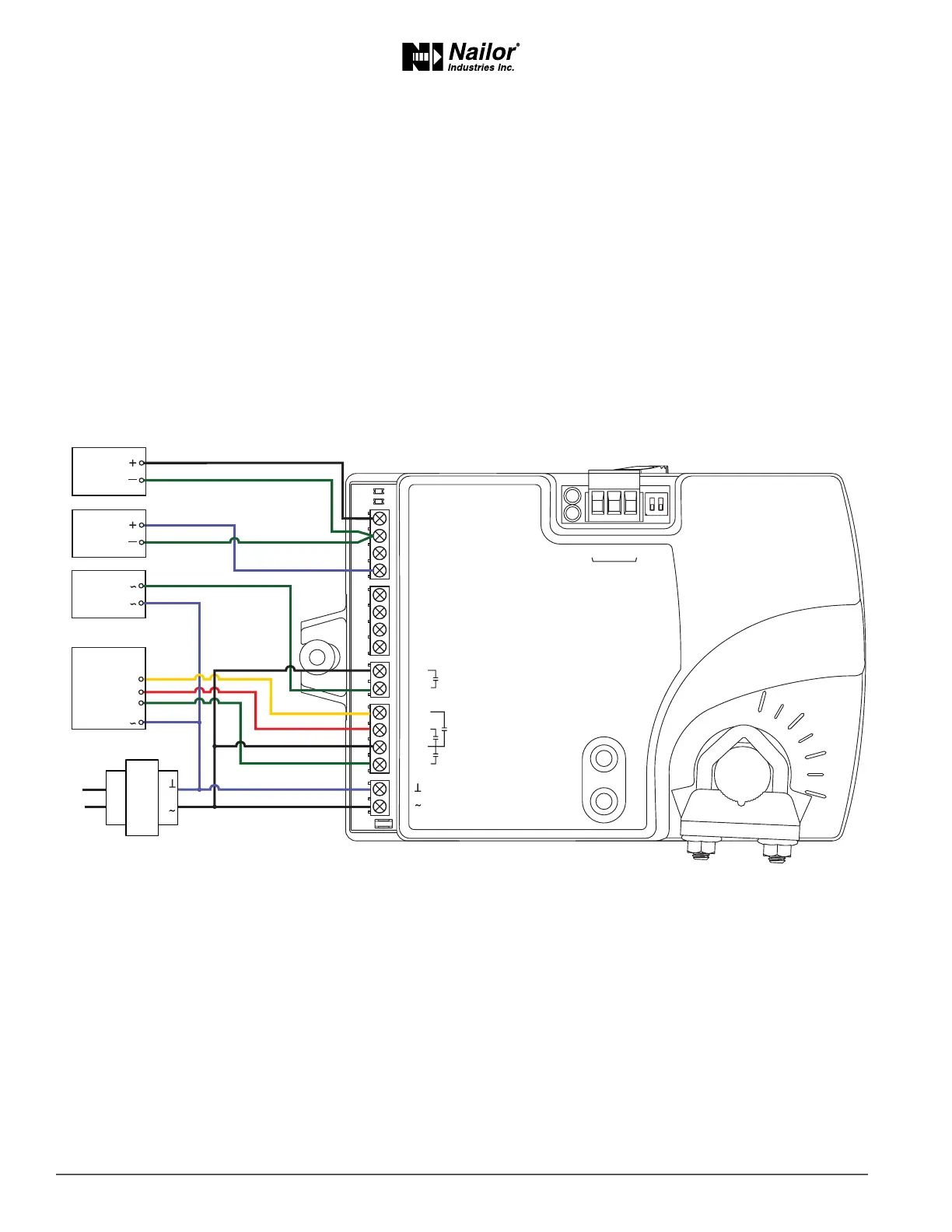
This applicaon is for BAC 8005-36 controller. The controller are congured to switch reheat units that are controlled with 24 volts
AC. Reheat units with up to three stages of reheat can be controlled by these controllers.
• For one-stage or electric reheat or hot water reheat with an on/o valve, use only output terminal BO6.
• For two-stage reheat use output terminals BO6 and BO7.
• For three-stage reheat use output terminals BO6, BO7 and BO8.
For cooling and heang, a duct temperature sensor is required for automac changeover.
When connecng the controller to a fan powered VAV terminal unit, the fan circuits must be compable with the following
specicaons.
• The fan start circuit is a 24 volt AC pilot duty output.
• The fan speed output is 0 – 10 volts DC.
Submial sheets for several variaons of this applicaon are available from the Resources page at www.nailor.com.
Figure7-2 BAC-8005-36(SingleDuct)withthree-stagereheat
ON CTS
1 2
COMM
READY
AI1
AI5
GND
AO4
AO3
SC
BO8
BO5
BO6
SC
BO7
24VAC
AI6
GND
AI7
T-STAT/
SENSOR
-A
+B
S
EOL
BACnet MS/TP
Fan
Speed
Duct
Temp
Sensor
Stage 1
Stage 2
Stage 3
24VAC
Fan start
Reheat
24 VAC