IOM-EZVAVINST
Date: 10-2016 Supersedes: 7-2016
Nailor reserves the right to change any information concerning product or specification without notice or obligation.
Page 38 of 48
Installation and Operation Manual
●
EZvav Digital Controls
DamperOperaon
Damper movement is determined by comparing the actual airow reading to the airow set points. If the actual airow is within
5% of the set point, no damper acon is iniated. Once within the 5% deadband, the actual airow must be outside a 7% deadband
before damper posion changes.
FanOperaon
The EZvav controllers support both series and parallel fan powered VAV units. For either type of fan operaon, the fan is controlled
through the following terminals.
• A binary output triac controls a 24-volt fan starng circuit. See the topic Conguring the VAV Terminal Unit opons on
page 17 for the procedure to congure the controller for a fan.
• A 0-10 volt DC analog output controls the speed of the fan. The output controls fan speed at either Min Fan Speed or Max
Fan Speed. See the topic Set the airow set points on page 19 for the procedure to set the fan speeds.
If the VAV unit is not congured for a fan, the two outputs are not used and remain inacve regardless of the occupancy state.
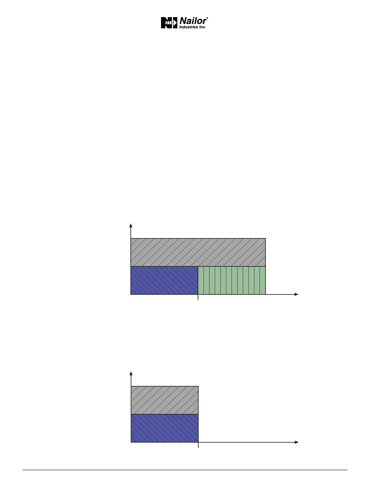
SeriesFan
If the controller is congured for a series fan, any me the Occupancy mode of the controller is set to either Occupied or Standby,
the fan runs connuously. The fan speed is set to Maximum Fan Speed when the state is Occupied and set to Minimum Fan Speed
when the state is Standby.
When the Occupancy state is Unoccupied, the fan starts and runs at minimum speed only on a call for heang. The fan starts when
the Heang loop is greater than 5% and stops when the Heang loop is less than 1%.
Figure8-2 Seriesfanoperaon
ParallelFan
If the controller is congured for a parallel fan, any me the Occupancy mode of the controller is set to either Occupied or Standby
and there is a call for heat, the fan runs connuously. The fan starts when the Heang loop is greater than 5% and stops when the
Heang loop is less than 1%.
When the unit Occupancy state is Unoccupied, the fan starts and runs at minimum speed only on a call for heang. The fan starts
when the Heang loop is greater than 5% and stops when the Heang loop is less than 1%.
Figure8-3 Parallelfanoperaon
UNOCCUPIED/
STANDBY
STANDBY
MAX FAN SPEED
MIN FAN SPEED
FAN OFF
OCCUPIED
HTG SP ROOM TEMP INCREASE
MAX FAN SPEED
MIN FAN SPEED
FAN OFF
OCCUPIED
HTG SP ROOM TEMP INCREASE
UNOCCUPIED/
STANDBY