IOM-EZVAVINST
Date: 10-2016 Supersedes: 7-2016
Nailor reserves the right to change any information concerning product or specification without notice or obligation.
Page 8 of 48
Installation and Operation Manual
●
EZvav Digital Controls
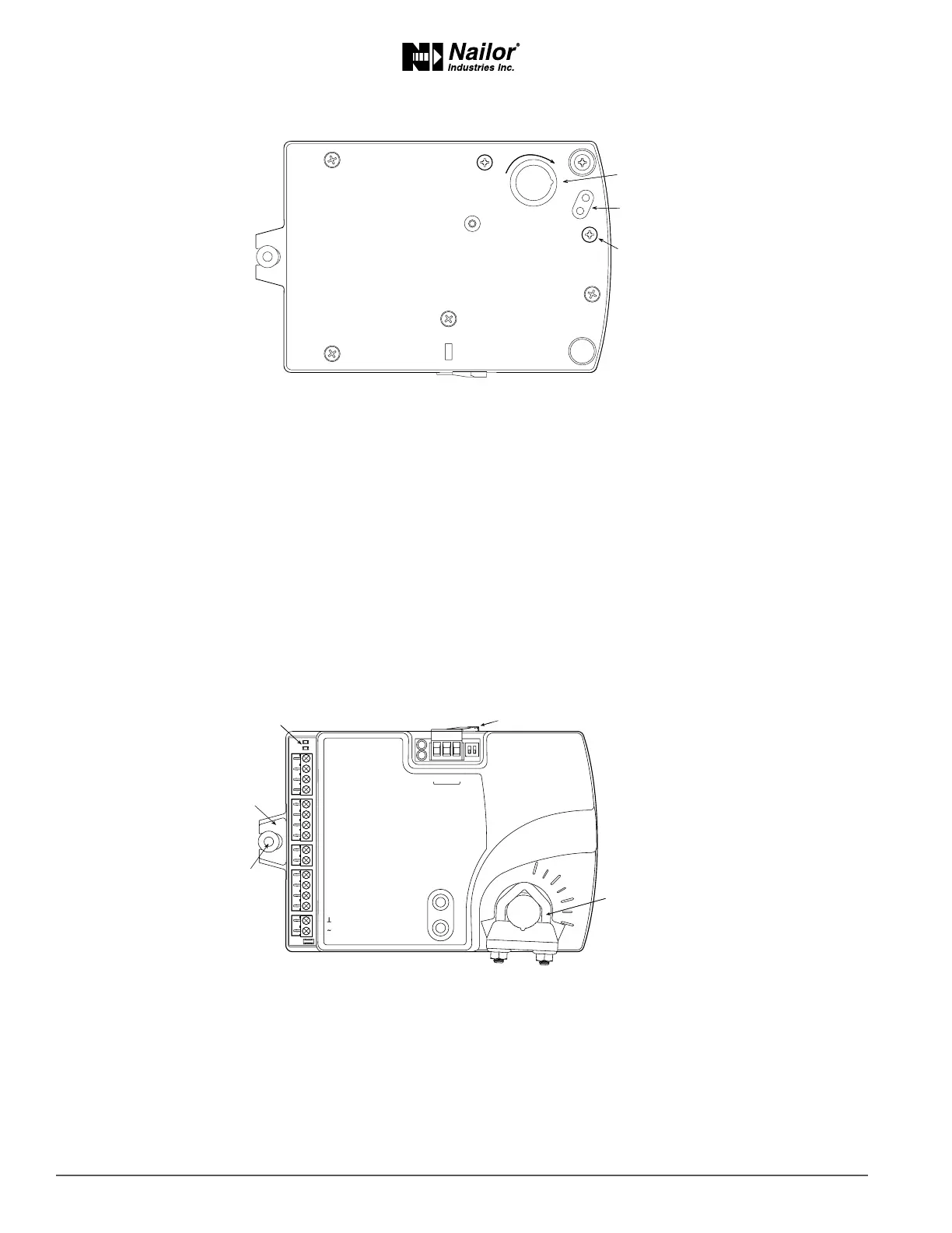
Figure2-1 Controllerrotaonlimitselecons
To set the rotaonal limits, do the following:
1. Turn the controller over so you have access to the back.
2. Manually rotate the actuator fully clockwise as viewed from the back.
3. Remove the stop screw from its storage locaon and clean any debris from the threads.
4. Insert the screw into the correct stop posion hole.
5. Tighten the screw only unl the head touches the plasc in the boom of the recess.
MounngonaVAVTerminalUnit
Mount the controller inside of a metal enclosure. To maintain RF emissions specicaons, use either shielded connecng cables
or enclose all cables in conduit.
Mount the controller directly over the damper sha. A minimum sha length of 2.0 inch (51 mm) is required.
Note: Nailor EZvav controllers are designed to directly mount to 3/8 to 5/8 inch (9.5 to 16 mm) round or 3/8 to 7/16 inch (9.5 to
11 mm) square damper shas.
Figure2-2 Controlandindicators
45
60
Position notch as shown
Stop position holes
Stop screw in storage
Rotate CW
ON CTS
1 2
COMM
READY
AI1
AI5
GND
AO4
AO3
SC
BO8
BO5
BO6
SC
BO7
24VAC
AI6
GND
AI7
T-STAT/
SENSOR
-A
+B
S
EOL
BACnet MS/TP
Status LEDs
Mounting
tab
Mounting
bushing
Gear clutch button
Drive hub
and V-bolt
Mount the controller as follows:
1. Manually rotate the damper on the VAV box to the fully closed posion.
2. On the controller, press the gear clutch buon and rotate the drive hub in the same direcon that closed the
damper. Turn the hub unl it reaches a rotaon limit, then rotate 2° in the opposite direcon and release clutch.
3. Loosen the nuts on the V-bolt unl the damper sha can t through the collar.
4. Place the controller over the damper sha.
5. Finger ghten the nuts on the V-bolt to posion the sha in the drive hub
6. Center the mounng bushing in the mounng tab and fasten it with a #8 sheet metal screw.
7. Evenly ghten the V-bolt nuts on the drive hub to 30-35 in-lbs (3.34 – 3.95 N.m).