IOM-EZVAVINST
Date: 10-2016 Supersedes: 7-2016
Nailor reserves the right to change any information concerning product or specification without notice or obligation.
Page 24 of 48
Installation and Operation Manual
●
EZvav Digital Controls
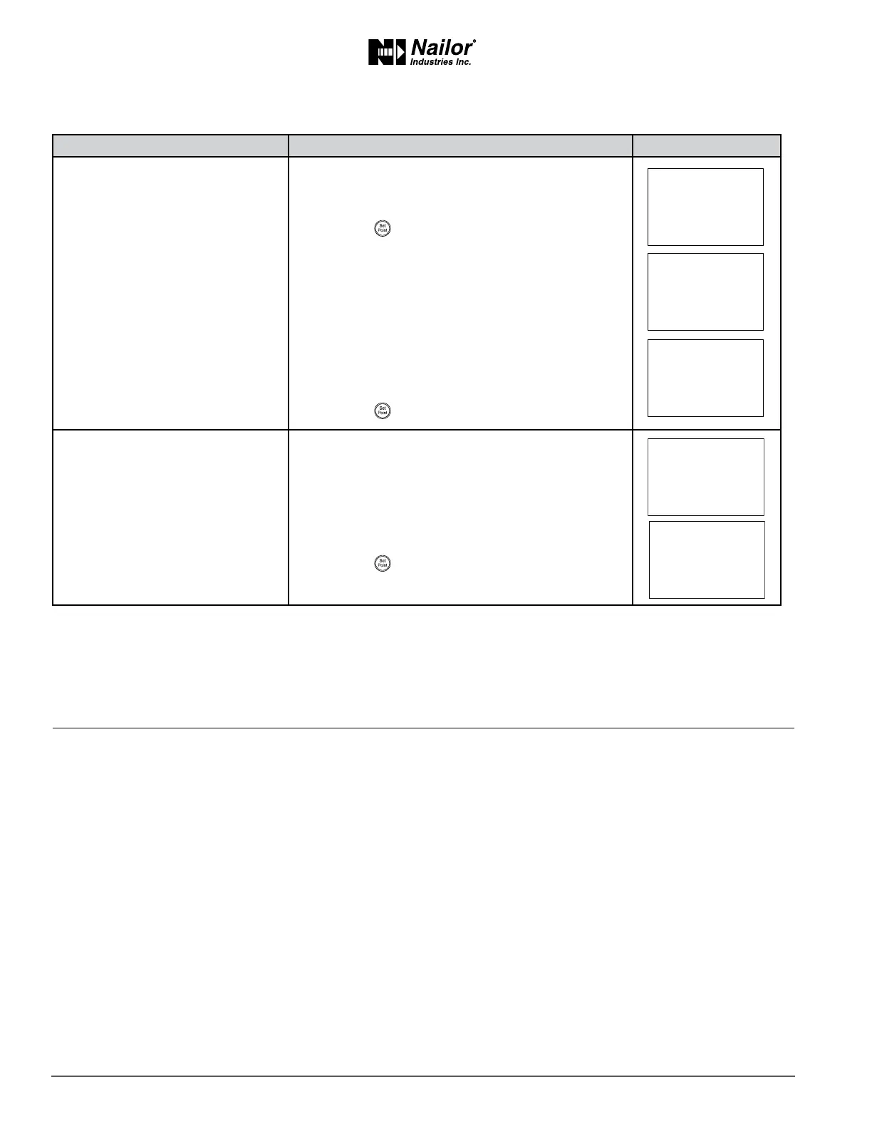
Proceduretorestoreapplicaon(connue)
PROCEDURE STEPS STEDISPLAY
2 Select the restore sengs display.
1. From the CNFG display, press the
∆
or
buons
to show the CNFG display.
2. Press the buon to select the CNFG opons.
The display changes to STPT.
3. Press the
∆
or buons to change the display to
RSTR.
Cauon: Choosing RSTR deletes all previously
entered values and returns the controller to
the manufacturer’s sengs. Only the BACnet
communicaons sengs will remain unchanged.
4. Press the buon to select RSTR.
3 Choose the applicaon.
1. Press the
∆
or buons to choose ENGLISH
or METRIC.
Metric The sensor displays temperature in Celsius and
uses metric values for units of measure.
English The sensor displays temperature in Fahrenheit
and uses English values for units of measure.
2. Press the buon to save the entry and advance to
the next funcon.
∆
∆
∆
Secon6:BalancingAirow
Topics in this secon are for control technicians or engineers who will be balancing the airow in the controllers.
The airow balancing procedure described in this secon requires the following items.
• Accurate method to measure airow.
• An STE-8001W36 or STE-8201W36 wall sensor. If the system does not include one of these sensors, temporarily disconnect
the installed sensor and connect an STE-8001W36 as a service tool.
• The engineering design specicaons for the minimum and maximum airow set points.
• Password 2 which is described in the topic Geng started with conguraon on page 14.
Users may change the acve heang and cooling set points without accessing the conguraon funcons. This procedure is
covered in the topic Changing the Room Set Point on page 13.
Note: If the VAV terminal unit is a heat only or cooling only unit, the airow set points for the unused mode must be set within
the range of the mode in use. Failure to set the unused set points correctly will result in unpredictable or erroneous air balancing
sengs. See Set the airow set points on page 19 for the procedure to adjust the set points.
Note: Starng the balancing procedure erases all previous airow correcon factors. The airow readings displayed by the
STE-8001W36 are the actual uncorrected airow readings as measured by the controller.
Tip: Once the following procedure is started, all steps must be completed in order.