IOM-EZVAVINST
Date: 10-2016 Supersedes: 7-2016
Nailor reserves the right to change any information concerning product or specification without notice or obligation.
Page 10 of 48
Installation and Operation Manual
●
EZvav Digital Controls
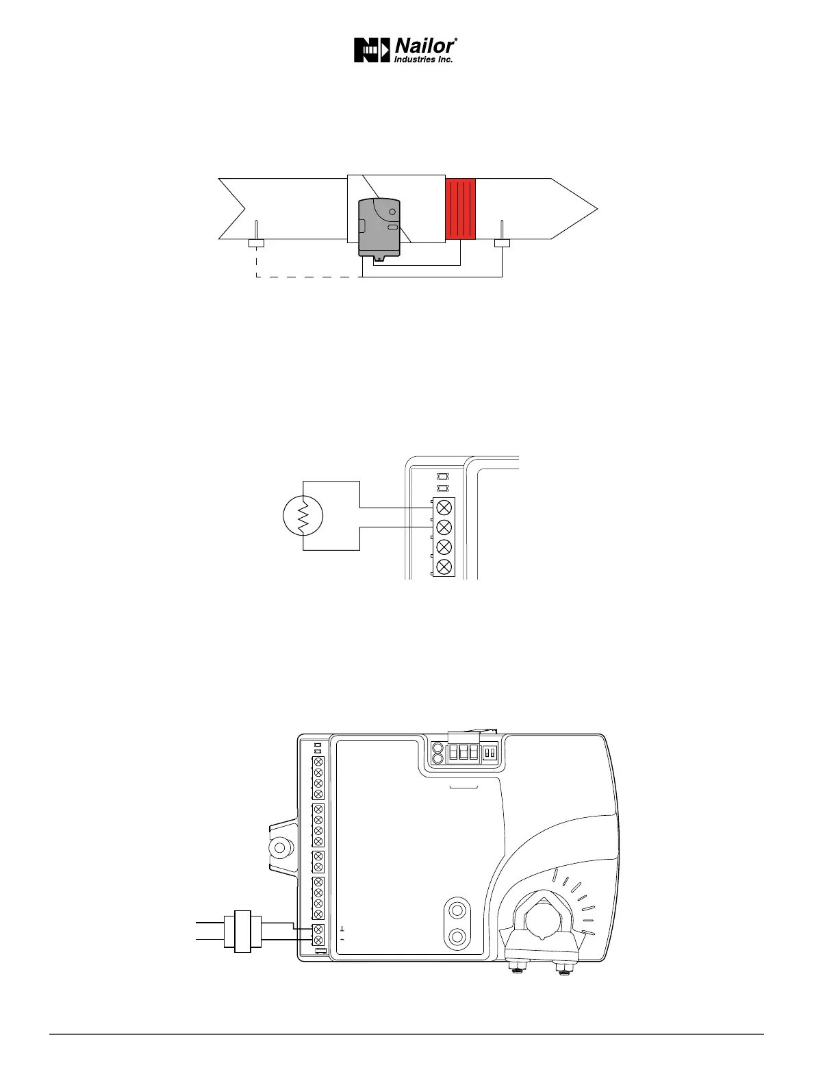
ConnecngaDATSensor
The Discharge Air Temperature sensor is required for automac changeover and for VAV terminal units with reheat.
Figure2-5 Dischargeairtemperaturesensorlocaon
Connect a 10 kΩ, Type 3 thermistor temperature probe to the discharge air temperature input. The input includes the internal
pull-up resistor. An STE-1401 sensor is suitable for this applicaon. Follow the instrucons supplied with the sensor for installaon,
or refer to pages 11-12 for this informaon.
• For DAT liming and reheat, install the sensor in the airow aer the reheat secon. See the topic, Advanced opons on
page 21 to enable discharge air temperature control.
• When the DAT sensor is used only to detect primary air temperature, the sensor can be placed in either locaon shown in
the Figure Discharge air temperature sensor locaon.
Figure2-6 Dischargeairtemperatureinputdetails
ConnecngPower
The controllers require a 24 volt, AC power source. Use the following guidelines when choosing and wiring transformers to the
controller.
• A Class – 2 transformer is supplied with each unit.
Connect the 24 volt AC power supply to the power terminal block on the lower right side of the controller. Connect the ground
side of the transformer to the ground terminal and the AC phase to the phase terminal. Power is applied to the controller when
the transformer is connected to power.
Figure2-7 Controllerpowerterminals
Maintenance
Nailor EZvav controllers require no roune maintenance. If necessary, clean with a damp cloth and mild soap.
T
COMM
READY
AI1
GND
AO4
AO3
24 VAC
Class 2
ON CTS
1 2
COMM
READY
AI1
AI5
GND
AO4
AO3
SC
BO8
BO5
BO6
SC
BO7
24VAC
AI6
GND
AI7
T-STAT/
SENSOR
-A
+B
S
EOL
BACnet MS/TP
DAT sensor
Preferred location
DAT sensor
Changeover only