IOM-EZVAVINST
Date: 10-2016 Supersedes: 7-2016
Nailor reserves the right to change any information concerning product or specification without notice or obligation.
Page 31 of 48
Installation and Operation Manual
●
EZvav Digital Controls
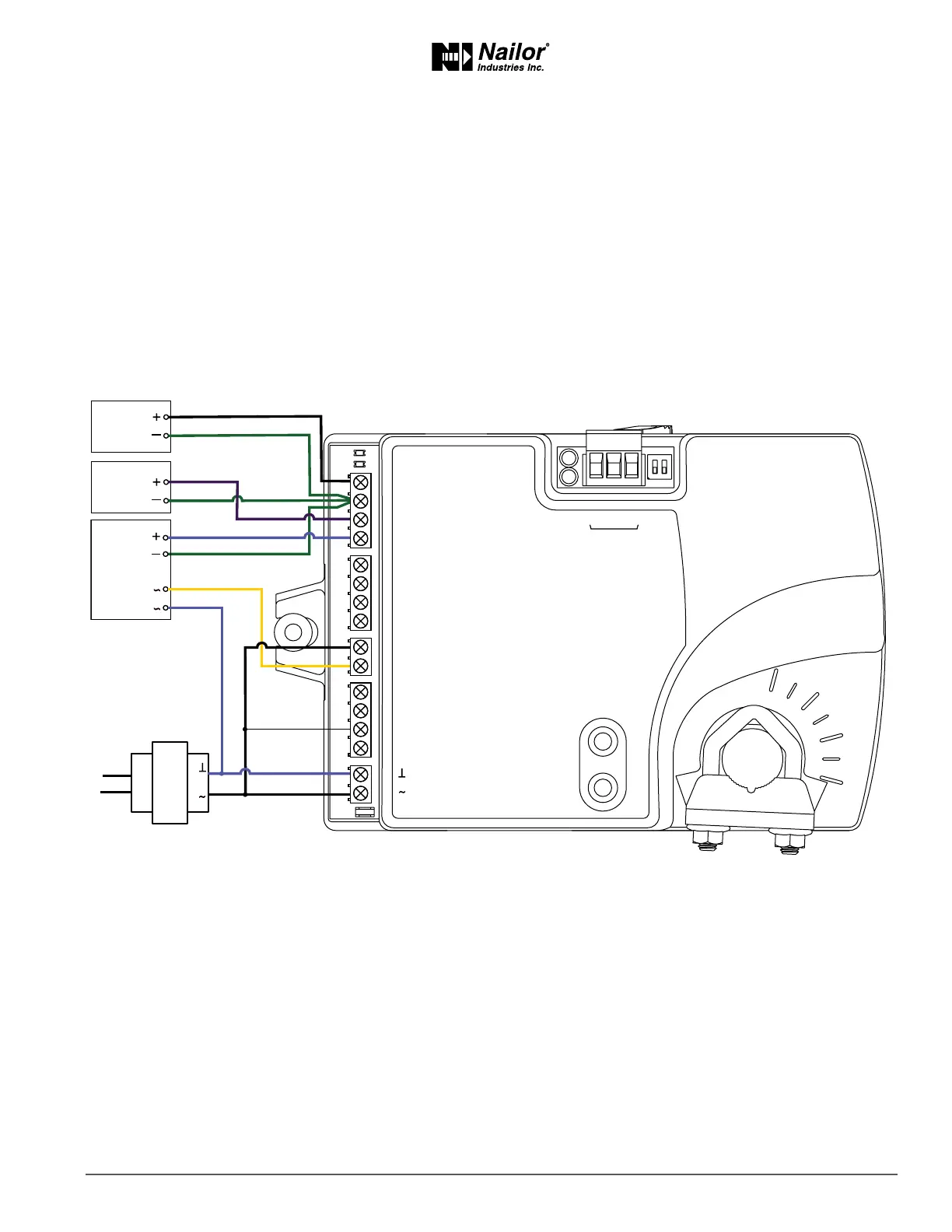
ModulangReheat
This applicaon is for a BAC-8005-36 controller. The modulang opon for reheat can control either an electric reheat unit with an
analog input or a modulang hot water valve. The analog reheat output at output terminal AO3 varies between 0 and 10 volts DC.
For cooling and heang, a duct temperature sensor is required for Discharge Air Temperature liming and automac changeover.
See the topic Advanced opons on page 21 for instrucons to enable Discharge Air Temperature liming.
When connecng the controller to a fan powered VAV terminal unit, the fan circuits must be compable with the following
specicaons.
• The fan start circuit is a 24 volt AC pilot duty output.
• The fan speed output is 0 – 10 volts DC.
Submial sheets for several variaons of this applicaon are available from the Resources page at www.nailor.com.
Figure7-3 Modulangreheat
ON CTS
1 2
COMM
READY
AI1
AI5
GND
AO4
AO3
SC
BO8
BO5
BO6
SC
BO7
24VAC
AI6
GND
AI7
T-STAT/
SENSOR
-A
+B
S
EOL
BACnet MS/TP
Fan
Speed
0-10 VDC
Duct
Temp
Sensor
Analog
Heat
24VAC
Fan start
24 VAC
Class 2
 Loading...