IOM-EZVAVINST
Date: 10-2016 Supersedes: 7-2016
Nailor reserves the right to change any information concerning product or specification without notice or obligation.
Page 41 of 48
Installation and Operation Manual
●
EZvav Digital Controls
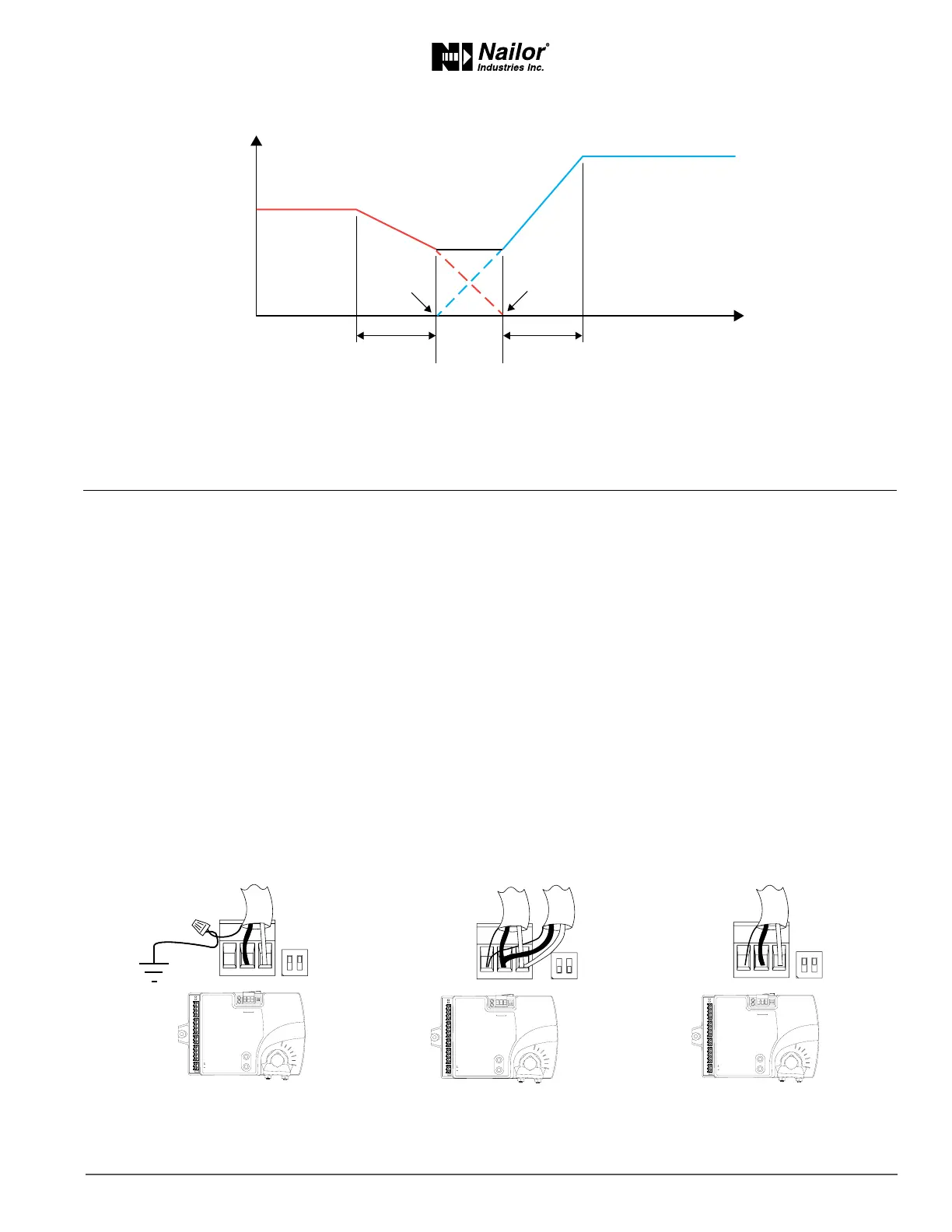
Figure8-6 Dualductsequence
Secon9:SystemIntegraonandNetworking
Topics in this secon cover integrang the controllers into a building automaon network. These are advanced reference topics
for control technicians and engineers.
The controllers can be installed as standalone controllers or they can be connected to a BACnet MS/TP network. The topics in this
secon are reference material for control technicians or engineers who are planning, installing, and seng up controllers that are
connected to a network.
In addion to the informaon in this secon, you will also need the following informaon.
• Detailed plans and drawings for the building automaon system.
• Informaon about the facility LAN including routers, switches, and network rewalls.
• Sequences of operaon for other BACnet devices that will monitor or interact with EZvav controllers.
Integraontopics
Connecng to an MS/TP network .....................................................................................................41
Seng up network communicaons ................................................................................................42
BACnet objects .................................................................................................................................44
ConnecngtoanMS/TPnetwork
EZvav controllers are BACnet MS/TP compliant controllers. Connect them only to a BACnet MS/TP network.
To enter the BACnet device instance, MAC address, and network baud, see the topic Seng up network communicaons on page 42
Figure9-1 MS/TPnetworkwiringandEOLswitches
Max. cooling airflow
Airflow increase
Max heating airflow
Dual duct
minimum
airflow
Room temp increase
HTG SPAN CLG SPAN
MIN
CLG
CFM
MIN
HTG
CFM
ON CTS
1 2
COMM
READY
AI1
AI5
GND
AO4
AO3
SC
BO8
BO5
BO6
SC
BO7
24VAC
AI6
GND
AI7
T-STAT/
SENSOR
-A
+B
S
EOL
BACnet MS/TP
S
+B
-A
ON
1 2
ON CTS
1 2
COMM
READY
AI1
AI5
GND
AO4
AO3
SC
BO8
BO5
BO6
SC
BO7
24VAC
AI6
GND
AI7
T-STAT/
SENSOR
-A
+B
S
EOL
BACnet MS/TP
S
+B
-A
ON
1 2
ON CTS
1 2
COMM
READY
AI1
AI5
GND
AO4
AO3
SC
BO8
BO5
BO6
SC
BO7
24VAC
AI6
GND
AI7
T-STAT/
SENSOR
-A
+B
S
EOL
BACnet MS/TP
S
+B
-A
ON
1 2
End of line controller
with grounded shield
EOL switches ON
Mid line controller
EOL switches OFF
with open shield
EOL switches ON
 Loading...