SCHEDULE TYPE:
PROJECT:
ENGINEER:
CONTRACTOR:
Nailor Industries Inc. reserves the right to change any information concerning product or pricing without notice.
DESCRIPTION:
• 18 ga. (1.31) galvanized steel
channel frame with 20 ga. (1.00)
casing components.
•
16 ga.
(1.61) galvanized
steel inclined opposed blade
dampers. 45° rotation. RH CW
to close. LH CCW to close.
• Separate outside ventilation air
inlet.
• Ultra-high efficiency ECM
fan motor. EPIC fan volume
controller.
• Multi-point averaging
Diamond Flow sensor. Supplied
with balancing tees.
• Universal access panels on all
4 sides.
•
3/4" (19) dual density
insulation, coated to prevent air
erosion, meets requirements of
NFPA 90A and UL 181.
•
Single point electrical and/or
pneumatic main air connection.
•
Discharge opening for
flanged
duct connection.
• Full enclosure for factory
mounted DDC and analog
electronic controls.
•
Choice of right or left-hand
primary inlet location. Hand
of
unit is determined by location
of primary inlet looking in
direction of airflow. Right-hand
illustrated.
OPTIONS:
Digital Controls:
q Factory mounted (supplied
by others)
q Field mounted (supplied by
others)
Liner:
q Steri-liner
q Steri-liner + Perforated metal
q Fiber-free
q Perforated metal
q Solid metal
q 1" (25) fiberglass
Other:
q Left-hand controls location
q Left-hand primary inlet
location
q Toggle disconnect switch
q Fan unit fusing
q 24/24V Isolation
transformer
q Cross Flow Sensor (not on
primary inlet)
q 'Q' Option – Induced
Air Inlet Attenuator. (not
available w/FN2 option).
q Top entry induced air inlet
q 1" (25) Throwaway filter
q 2" (51) MERV 8 filter
q Hanger brackets.
q 1/4-turn fasteners (access
panel)
DATE B SERIES SUPERSEDES DRAWING NO.
2 - 6 - 23 3500 11 - 15 - 22 35S-OAI-2
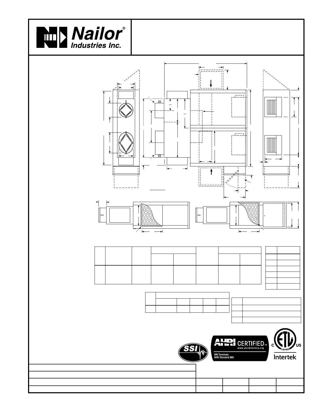
FAN POWERED TERMINAL UNIT WITH
OUTSIDE AIR INLET • EPIC ECM MOTOR
SERIES FLOW • CONSTANT OR VARIABLE VOLUME
MODELS: 35S-OAI, 35SW-OAI AND 35SE-OAI
UNIT SIZE 7
Model 35S-OAI • Basic Unit
Dimensional Data
Unit
Size
Primary
Inlet Size
Outside
Inlet Size
Induced Air Inlet
Outlet
Discharge
DW x DH
Filter Size
Side (std.)
IW x IH
Top (opt.)
TL x TW
Side Inlet
(std.)
Top Inlet
(opt.)
7
12**, 14**, 16**
(203**, 254**,
305**)
6, 7, 8, 10
(152, 178,
203, 254)
12 x 14
(305 x 356)
Qty. of 2
8 1/2 x 22
(216 x 559)
Qty. of 2
39 1/4 x
11 1/2
(997 x 292)
14 x 16
(356 x 406)
Qty. of 2
10 x 25
(254 x 635)
Qty. of 2
Size W1 or W2
6 12 (305)
7, 8 14 (356)
10 16 (406)
12** 19 (483)
14** 20 (508)
16** 24 (610)
Oval Inlet Dimensions
Primary/Inlet
Dimensions
6 3/4"
(171)
5 3/4"
(146)
14" (356)
A
W3
+
11 1/2"
(292)
PW
DIA. =
NOM.
– 1/8"
(3)
PH
10" (254)
12" (305)
FAN
1" (25)
DH
DW
52"
(1321)
FAN
13 1/4"
(337)
5"
(127)
(197)
18"
(457)
RIGHT-HAND
PRIMARY AIR
VALVE CONTROL
ENCLOSURE
OPTIONAL INDUCED AIR FILTER
IW
IH
LEFT-HAND
PRIMARY AIR
VALVE CONTROL
ENCLOSURE
L
C
TL
TW
OPTIONAL
TOP
INDUCED
AIR
INLET
W2
W1
W2
2
W3
2
L
C
L
C
W3
PRIMARY
AIR
INLET
5 3/4"
(146)
OPTIONAL INDUCED AIR FILTER
IW
IH
17"
(432)
HINGED FAN
CONTROLS
ENCLOSURE
14" (356)
IH + 2" (51)
IW + 2" (51)
INDUCED
AIR
'Q' OPTION INDUCED
AIR ATTENUATOR
PERFORATED
DIFFUSION
BAFFLE
OUTSIDE
AIR INLET
INDUCED
AIR
15"
(381)
OPTIONAL
90° FN2
HINGED FAN
CONTROLS
ENCLOSURE
5 1/2"
(140)
W3 = W1 + W2
A =
W1 + W2
2
Electrical Data
Unit
Size
EPIC ECM Motor FLA
Motor HP 120V 208V 240V 277V
7
*
15.9 10.5 9.9 10.0
**
Flat oval inlets
Size PW x PH
12** 12 13/16 x 9 13/16 (325 x 249)
14** 16 1/16 x 9 13/16 (408 x 249)
16** 19 3/16 x 9 13/16 (487 x 249)
*
The ECM is a variable horsepower motor.
Refer to Selectworks schedule for actual
power consumption.
FLA = Full load amperage. All motors are single
phase/60 Hz.
Seismic Certification:
q Seismic Source International (Standard)
q HCAI (formerly OSHPD, California)
q Special Features: _________________ .
q FN2 90° Line Voltage
Enclosure
q FN3 Remote Line
Voltage Controls
Enclosure
(See submittal FN3)
q Dust tight enclosure
seal
q Remote user
disconnect
Listed
Page 1 of 2. For heat options; see page 2.
Dimensions are in inches (mm).
 Loading...